Software Reaction Time: Introduction
Introduction
According to Oxford Reference, reaction time is “The period of time between the detection of a stimulus at a sensory receptor and the performance of the appropriate response by the effector organ.”. This is a widely used term in psychology and related fields.
In computer software and electronics, there are a few different terms for the same type of measurement, the time difference between two events.
- response time: from an application’s receive of a request to serve it (first byte or all), usually in milliseconds or seconds.
- interrupt latency: from assertion of an interrupt to the start of the interrupt service routine, usually in microseconds or milliseconds.
- delay (e.g. propagation delay): from an input signal’s application to an input port to the output signal’s appearance at output port, it may vary but for the purpose of this post, it is in nanoseconds range, but it can be picoseconds (or less) or microseconds (or more).
(this is not all, there are more terms with slighly different meanings)
My latency posts, albeit their usefulness, related to interrupt latency of real-time linux kernels on Raspberry Pi 3B+ and 4, were popular reads. This, and a few other things, made me think how this property can be measured more properly.
So the problem I would like to focus is this: how you can easily, accurately and precisely measure the reaction time of a software plus hardware system that is reacting to physical events (stimulus) and producing physical actions (response). There are so many examples of this in robotics or in IoT applications. Depending on how you define or relax the definition of stimulus and response, it can also cover narrower or broader range of applications.
Instead of using the terms above, I decided to use reaction time, which is I think not commonly used for software, but I think best describes the situation here.
Nothing above may be new to you but the problem is the difficulty of doing this measurements. You can easily do one or two measurement using a signal generator and an oscilloscope, but these measurements are (only) useful when they have a statistical meaning, and you need thousands of measurements for this, which is easily beyond any manual effort. Also, it is not possible to do measurements properly using only a software on a general purpose computer because there are always some uncertainties in software in milliseconds (or microseconds) range. So there is a need for a pure hardware solution for this problem.
Design
How to design this measurement system ?
Lets define two terms first.
- SUT: System under test whose reaction time is measured
- MS: Measurement system that measures the reaction time of SUT
Not surprisingly the best MS is a software + hardware hybrid like a digital oscilloscope. The actual measurement has to be done by the hardware but the interface with the hardware is done using a software. An FPGA is the most straightforward answer to this. I think especially SoCs (my favorite is Xilinx Zynq) is very suitable, since the measurement logic can be implemented in the programmable hardware (PL) and the interface can be implemented in the general purpose processing system (PS). In the simplest case, the software only needs to configure the measurement logic, then initiate and read the measurement values and then show the measurement results somehow.
Prototype
Using an FPGA is a very flexible and powerful way to do this, but doing something with an FPGA is not an easy task if you do not already have some experience. So instead of doing this as a prototype, I searched for already available ready-to-use products that does something similar.
There are industrial products that does counting, which can be used for time measurement, and I decided to use a Measurement Computing USB-CTR04 high-speed counter. This device contains an FPGA, that have 4 hardware counters running at 48 Mhz and also some digital I/O. This is more than enough for a prototype.
CTR04 has (naturally) a proprietary FPGA implementation but it has an open source MCC Universal Library for Linux. The communication with CTR04 is over USB. I use this library and wrote a small program for configuring, initiating and reading the measurements and then displaying/saving them. Because the counter is implemented in the hardware, it is very precise and accurate with a maximum of 20.83 ns resolution (1/48Mhz). It has a few other modes but I am using the TIMING measurement mode which counts (at 48 Mhz) between the rising edge of two signals at its CIN (Counter In) and CGT (Counter Gate) terminals. CIN will be the stimulus (to SUT) input, and CGT will be the response (from SUT) input. In addition to CIN and CGT, I also use two digital I/O pins (START and STOP), to implement a simple protocol for measurements.
Basically this is my plan:
               |---------|          |----------|
|--------|     | CTR04   |          | SUT      |
| PC     |     |         |          |          |
|    USB |<--->| USB     |          |          |
|--------|     |     CGT |<-----|   |          |
               |     CIN |<--|  |   |          |
               |         |   |  |   |          |
               |   START |---+--|-->| Stimulus |
               |    STOP |<-----+---| Response |
               |---------|          |----------|
CTR04 is TTL (5V) compatible, so this prototype is OK only if SUT is also TTL compatible.
All signals are active high.
Measurement Protocol
To do measurements repeatedly, a simple protocol is needed. This 2-wire protocol (START and STOP signals) is what I am using:
Initial Configuration
- I assume SUT starts first, it de-asserts STOP to indicate it is ready for a measurement and waits for START.
- Then the control software of CTR04 starts and CTR04 is configured. No measurement is started yet.
Hardware Counter in CTR04
- CTR04 Hardware Counter runs autonomously, waiting a rising edge on CIN, by which it starts counting (at 48 MHz).
- It stops counting when a rising edge at CGT is detected.
CTR04 Controller Software running at PC
After configuration, the following steps run in a loop.
- Waits for de-assertion of STOP, this indicates SUT is ready for measurement.
- Asserts START, this causes the timing measurement to start.
- Waits for assertion of STOP, which causes the timing measurement to stop.
- Reads the counter value of CTR04 and stores it.
- De-asserts START, to indicate this measurement is completed.
Software in SUT
The following steps run in a loop.
- De-asserts STOP, to indicate SUT is ready for next measurement
- Waits for assertion of START
- Starts processing.
- Asserts STOP
- Waits for de-assertion of START, this indicates the measurement is completed
Signals
Below are two screens from the oscilloscope for the signals mentioned above. D0 is START and D2 is STOP.
The upper part is the actual capture and the lower part is a zoom (the white rectangle in upper) view.
The first screen (lower part) is showing START is followed by STOP.
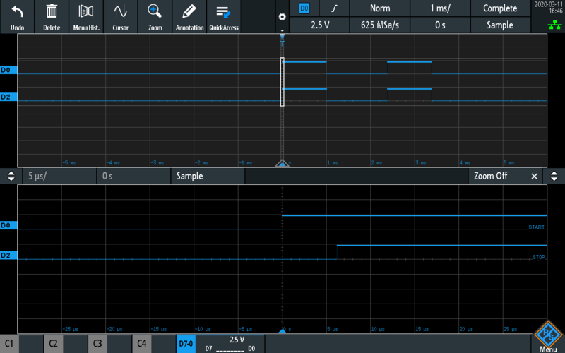
START signal
The second screen (lower part) is showing START is de-asserted and then STOP is de-asserted.
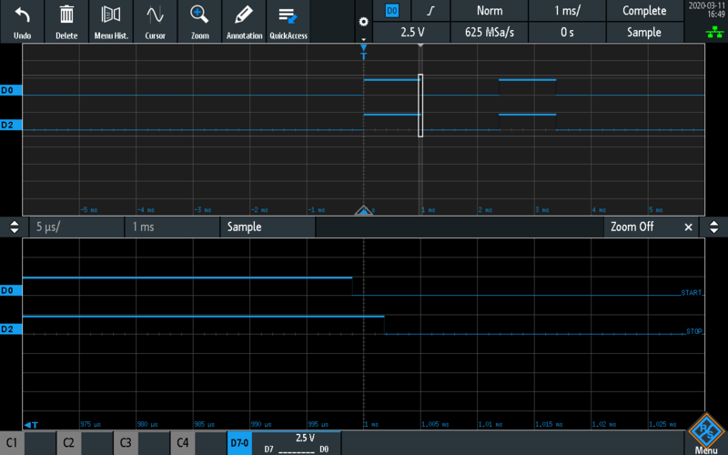
STOP signal
You probably wonder if the measurement (START to STOP) is only 6 microseconds, why the STOP and the START is asserted (and de-asserted) for so long (1-2 milliseconds). This is because the digital I/O of CTR04 cannot be switched that quickly (specified as maximum 8000 times/second). This affects the time it takes to complete many measurements but it does not change the essentials of how the system works.
Prototype for a Raspberry Pi SUT
A slight modification is needed if you are using a SUT not compatible with TTL, such as LVTTL (3.3V) compatible Raspberry Pi. In this case, there is a need to use level shifters, and I am using CD40109B for that. In Raspberry Pi, I am using GPIO 27 as stimulus input or start, and GPIO 22 as response output or stop.
Although it might not be needed, I use two CD40109B, one for high-to-low level shift (5V to 3.3V), one for low-to-high level shift (3.3V to 5V). Because CD40109B has a propogation delay around 100-200 ns, and CTR04 is TTL so LVTTL compatible, I am using the level shifter immediately after the driving pin (OUT and GPIO 22) and using the level shifter output to drive the corresponding pins at CTR04 (IN, CIN, CGT) and Raspberry Pi (GPIO 27). This eliminates the propagation delay to affect the start of the counter, it will start at the same time the signal arrives to GPIO 27 (Raspberry Pi stimulus input). However, because there is a level shifter after GPIO 22 (Raspberry Pi response output), there will be a delay for this to arrive CGT to stop the counter. Fortunately, this delay is quite predictable, small or may not matter if you are measuring reaction times in the milliseconds range, and the measurements can be corrected (delay can be subtracted from the measured time). For CD40109B, the propagation delay is 122ns -measured with an oscilloscope (see the figure below, propagation delay is from cursor 1 to cursor 2)- in this configuration (when high-level shifting from 3.3V to 5V).
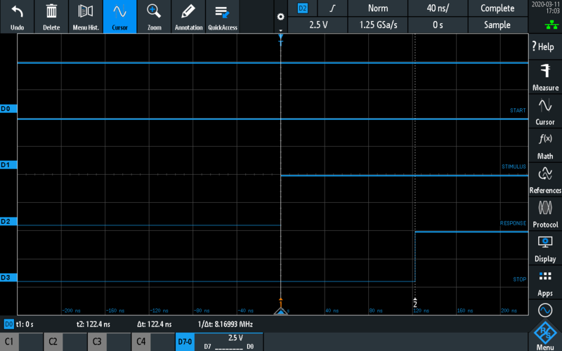
CD40109B 3.3V to 5V Low-To-High Propagation Delay
So the actual prototype is like this:
               |---------|                |--------------|
|--------|     | CTR04   |                | Raspberry Pi |
| PC     |     |         |                |              |
|    USB |<--->| USB     |                |              |
|--------|     |         |                |              |
               |     CGT |<--------|      |              |
               |     CIN |<-----|  |      |              |
               |         |      |  |      |              |
               |   START |--LS--+--|----->| GPIO 27      |
               |    STOP |<--------+--LS--| GPIO 22      |
               |---------|                |--------------|
CTR04 is USB powered, but the LSes requires both 5V and 3.3 power supply. Raspberry Pi also requires a USB or 5V power supply. I am using a three channel power supply to power all of these including Raspberry Pi.
Next
I will publish the measurements of a few simple Python program controlling GPIOs on Raspberry Pi.
This work is licensed under a Creative Commons Attribution-NonCommercial-ShareAlike 4.0 International License.