micro:bit (nRF51, Cortex-M0) GPIO toggling
Introduction
This is the first experiment of a potential series of posts related to lateny in computer systems. I needed to generate a pulse train (square wave or PWM), and I had a micro:bit, then I wondered how quick you can toggle the digital outputs of the micro:bit to generate such a signal. Basically I would like to write a 0 and then a 1 to a digital output, and repeat this forever, and I would like to see the frequency of the pulse train it generates and how different programming levels or abstractions affect this. I have done five experiments.
It is definitely a theoretical maximum but since the processor is clocked at 16 Mhz, GPIO toggling by software can, I think, be done at maximum 16/3~5.3 Mhz, assuming writing 1 and writing 0 and then looping back to writing 1 can each be done in a single cycle. I examine what maximum GPIO toggling frequency is possible in this post.
Setup
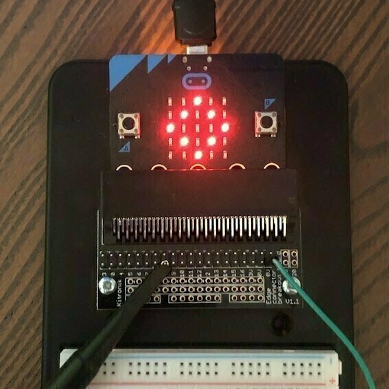
All experiments in this post is done with a BBC micro:bit (v1.5), which uses a Nordic Semiconductor nRF51822-QFAA Application Processor consisting of an ARM Cortex-M0 Processor at 16 Mhz. This processor does not have a special PWM feature, so a PWM signal has to be created using normal hardware features.
I decided to use pin P8 on micro:bit which is connected directly to P0.18 on nRF51822.
I have two micro:bit boards. One is running the standard firmware, where a hex binary program can be copied to the MICROBIT folder, which is mounted when it is connected to the computer, and then it is automatically flashed to the board. The other micro:bit is running a specific Segger firmware which enables J-Link OB (On Board). I use this board for the experiments where I use Segger Embedded Studio to write the programs and use the J-Link connection to flash the program to the board.
Both micro:bit boards are connected to a Kitronik Edge Connector Breakout Board during experiments and the corresponding pin on the breakout board is connected to the oscilloscope probe. Both boards are powered from the PC USB port.
All the measurements are done with a Rohde & Schwarz RTB2004 300 MHz 2.5GS/s oscilloscope using a RT-ZP03 300 Mhz 10:1 probe.
Experiment 1: makecode: digital out
makecode is I think a great environment, especially for kids and beginners. So the first experiment is very simple, just write 1 and 0 in the forever block.
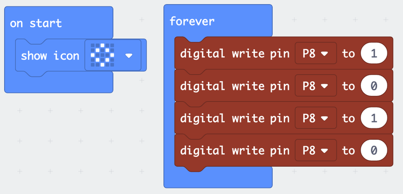
You probably wonder why there are two pairs of setting (the pin to 1) and clearing (setting pin to 0), it will be clear when you see the result now:
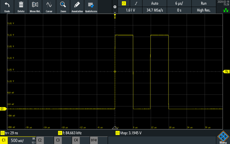
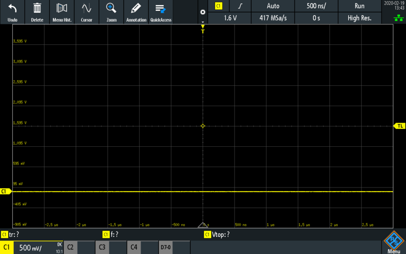
It looks like it is possible to generate a pulse train close to 100 kHz, however this is not the whole picture. You see after the second pulse there is no third, which is normally expected since the code is in the forever block. If it is zoomed out:
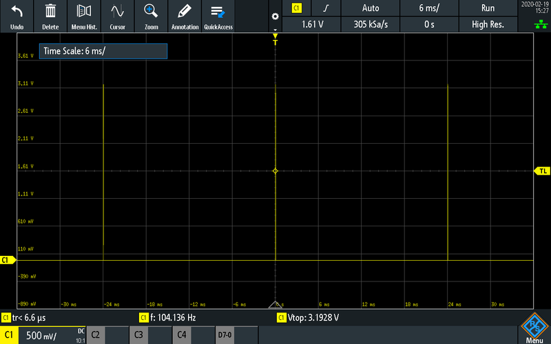
something strange going on, there is a very long period of silence between the pulses, around 24ms. The period of one pulse is around 12us, so there is a 1000x fold difference.
Basically this tells me:
The maximum GPIO toggling frequency you can achieve like this could be just under 100Khz.
However, the forever block does something before or after executing the blocks, so effectively, you can only reach under 50Hz.
Experiment 2: makecode: analog out or PWM
nRF51 does not have a dedicated PWM output capability, but PWM can be simulated by different means. makecode has two particular blocks (analog set period and analog write) for this purpose. Although the name is analog write, this does not write an analog voltage but changes the average voltage (so duty cycle) of a simulated PWM signal, and writing the middle value 512 means it is 50% duty cycle, like a square wave. analog set period sets the period of PWM signal and it is specified in microseconds. Here is the program:
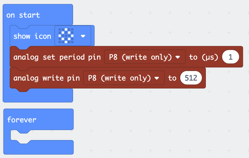
So the expectation is if the period is set to 1us like above, a 1MHz square wave (50% PWM) should be generated. However:
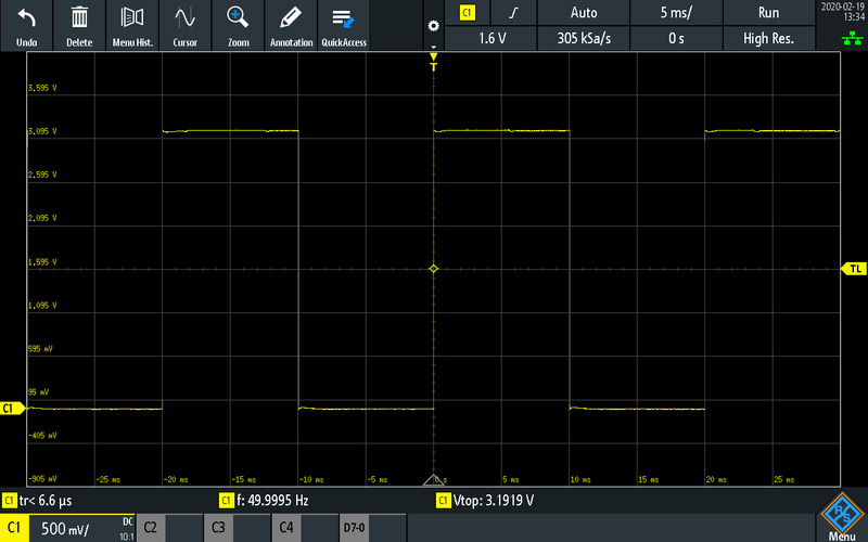
this is very strange since 50Hz is very small even if it is unable to make 1 Mhz. In the micro:bit programming guide, there is a note for analog set period saying: “Before you call this function, you should set the specified pin as analog.”, and it seems it is very important, it functions correct only if this is called after doing an analog write, so the code has to be:
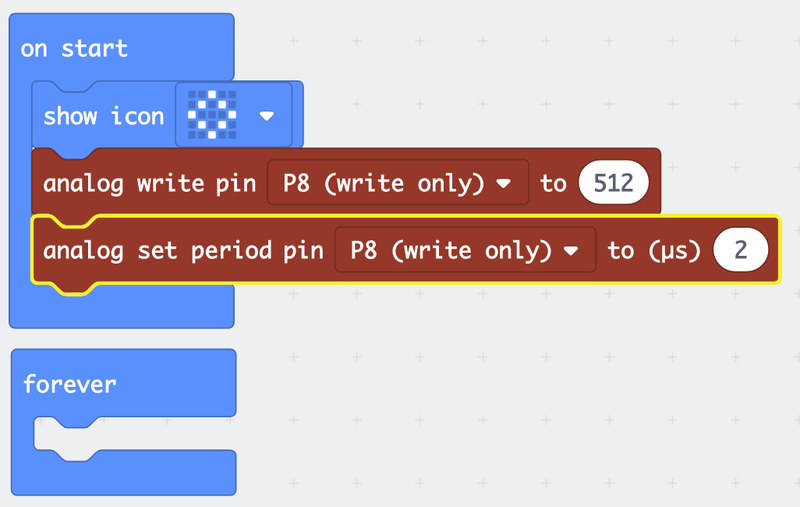
you see I changed 1us to 2us also, because there is no output with 1us, it seems it is not working with 1us, but it is fine with 2us:
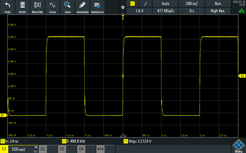
This shows a 500kHz pulse train or PWM signal is possible using this method.
In case you wonder, below is what happens if 1us is used, there is literally no signal at all. I am not sure if this is a bug or it is normal:
Experiment 3: micro:bit runtime: digital out
If you would like to write low level code for micro:bit, the first option is to use Lancaster University’s micro:bit runtime and write C/C++ code. This runtime is pretty easy to install and use. From what I understand, makecode also translates the blocks to a code which uses this runtime.
micro:bit runtime is built on ARM mbed platform and Nordic nRF51 SDK. So it is not directly accessing the hardware but it is pretty close.
So for this experiment, I just wrote a few lines of code:
##include "MicroBit.h"

MicroBitPin pin(MICROBIT_ID_IO_P8, MICROBIT_PIN_P8, PIN_CAPABILITY_DIGITAL);

int main()
{
    while (1)
    {
        pin.setDigitalValue(1);
        pin.setDigitalValue(0);
    }
}
As far as I understand from the source code of this runtime, MicroBitPin object holds a reference to an mbed object, and setDigitalValue method above basically calls mbed methods which goes to hardware. This program results:
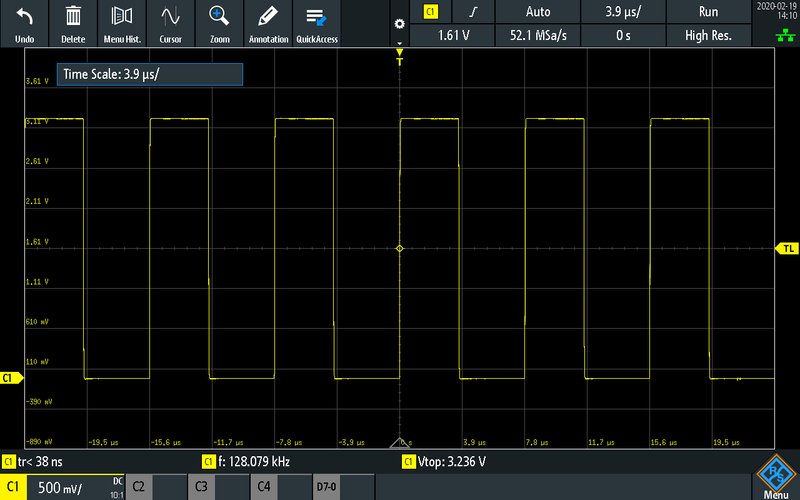
a signal at 128 kHz. However, be aware that it might be misleading, because I am not sure if yt build produces a debug or a release build.
The makecode program (experiment 1) actually generates the same code for digital out (makecode sourcecode is open, you can see how things are implemented). The code below is from pins.cpp in Microsoft pxt-microbit repo.
##define PINOP(op) \
      MicroBitPin *pin = getPin((int)name); \
      if (!pin) return; \
      pin->op

/**
* Set a pin or connector value to either 0 or 1.
* @param name pin to write to, eg: DigitalPin.P0
* @param value value to set on the pin, 1 eg,0
*/
//% help=pins/digital-write-pin weight=29
//% blockId=device_set_digital_pin block="digital write|pin %name|to %value"
//% value.min=0 value.max=1
//% name.fieldEditor="gridpicker" name.fieldOptions.columns=4
//% name.fieldOptions.tooltips="false" name.fieldOptions.width="250"
void digitalWritePin(DigitalPin name, int value) {
		PINOP(setDigitalValue(value));
}
so when you use digital write block it is actually translated into this runtime code, same as what I do above.
This is definitely much better than the first experiment but it is not as good as the second one. The second one is probably doing something special, and we will see what it does soon, in experiment 5.
Experiment 4: low-level digital out
What else can be done ? Instead of micro:bit runtime, ARM mbed can be used or hardware can be programmed directly. Accessing hardware directly is not difficult, but there has to be a toolchain to generate a binary image (hex etc.) to flash the board. Maybe it is possible to do this with micro:bit runtime, using only the toolchain, but I choose to use Segger Embedded Studio. There are also sample projects in the Segger BBC bicro:bit J-Link Upgrade site so I do not need to manually configure anything. I simply modify the Segger Microbit_LEDBlink example.
The program below is also very simple (the structures are taken from the Segger Microbit_LEDBlink example). In main, it first waits for clocks to stabilize, this is needed before running any code, and then runs a similar infinite loop, writes 1 to P0.18 and then writes 0. The details of registers can be found in the nRF51 Series Reference Manual.
##define GPIO ((GPIO_REGS*)0x50000000)
##define CLOCK ((CLOCK_REGS*)0x40000000)

typedef struct {
  volatile unsigned int aDummy0[321]; // this is just for jumping to 0x504
  volatile unsigned int OUT;          // 0x504 Write GPIO port
  volatile unsigned int OUTSET;       // Set individual bits in GPIO port
  volatile unsigned int OUTCLR;       // Clear individual bits in GPIO port
  volatile unsigned int IN;           // 0x510 Read GPIO port
  volatile unsigned int DIR;          // Direction of GPIO pins
  volatile unsigned int DIRSET;       // Setting DIR register
  volatile unsigned int DIRCLR;       // Clearing DIR register
  volatile unsigned int aDummy1[120]; // this is just for jumping to 0x700
  volatile unsigned int PIN_CNF[31];  // 0x700 Configuration of pin 0-31
} GPIO_REGS;

typedef struct {
  volatile unsigned int HFCLKSTART;      // 0x000 Start HFCLK crystal oscillator
  volatile unsigned int HFCLKSTOP;       // Stop HFCLK crystal oscillator
  volatile unsigned int LFCLKSTART;      // Start LFCLK source
  volatile unsigned int LFCLKSTOP;       // Stop LFCLK source
  volatile unsigned int CAL;             // 0x010 Start calibration of LFCLK RC oscillator
  volatile unsigned int CTSTART;         // 0x014 Start calibration timer
  volatile unsigned int CTSTOP;          // 0x018 Stop calibration timer
  volatile unsigned int aDummy[57];
  volatile unsigned int HFCLKSTARTED;    // 0x100 16 MHz oscillator started
  volatile unsigned int LFCLKSTARTED;    // 32 kHz oscillator started
  volatile unsigned int Dummy1;
  volatile unsigned int DONE;            // Calibration of LFCLK RC oscillator complete event
  volatile unsigned int CTTO;            // Calibration timer timeout
} CLOCK_REGS;

##define b18 (1uL<<18);

int main(void) {

  // start HighFrequencyClock HFCLK and wait until it is started
  CLOCK->HFCLKSTARTED = 0;
  CLOCK->HFCLKSTART = 1;
  while (CLOCK->HFCLKSTARTED == 0);
  CLOCK->HFCLKSTARTED = 0;

  // started

  GPIO->DIRSET = b18;
  GPIO->PIN_CNF[18] = 0x33;

  while (1) {

    GPIO->OUTSET = b18;
    GPIO->OUTCLR = b18;

  }

  return 0;

}
So how does this perform ?
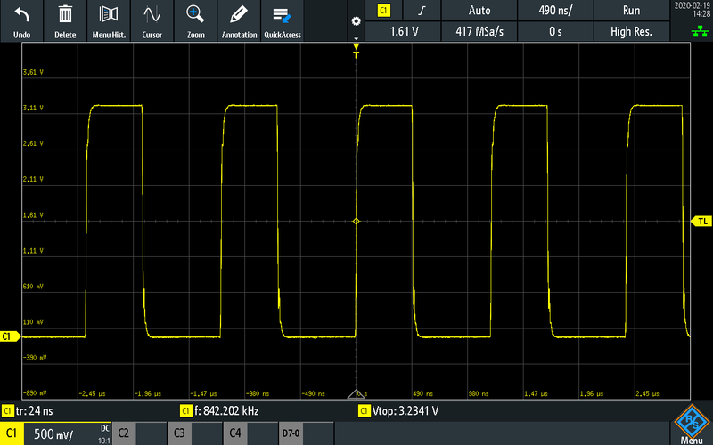
at 842 kHz. This is easily the best method, and it is not finished yet, because I used Debug build for this. I looked at the disassembled code, and there were 14 instructions implementing this loop (while, set outset, set outclr), which should be much simpler than that. So I changed it to Release config, and tried again:
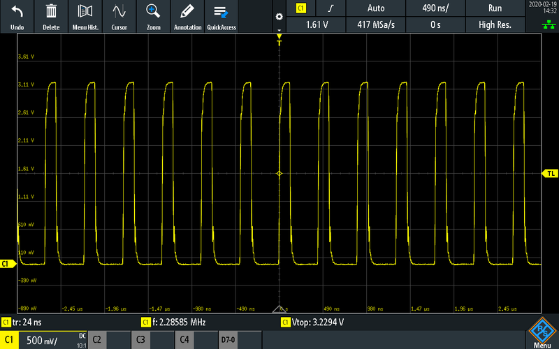
now it is 2.28 Mhz, the best result until now. Looking at the disassembly output, it is like this:
label:
str r2, [r3, r0]
str r2, [r3, r1]
b label
the while loop is now implemented with only 3 instructions, two stores and one branch. Like I said in the beginning, theoretical maximum in this case would be 5.3 MHz, but probably instructions are not single cycle and/or accesing the bus for the peripheral device is taking longer. Still, this result is I think pretty cool, it is almost half of what the theoretical maximum is.
I do not know if this result can be beaten, but lets try, something a bit different.
Experiment 5: low-level PWM
The only way to beat experiment 4 is to use something with hardware support. One (and probably only) way to do this in this particular processor is to use GPIO tasks and events (GPIOTE) with a timer and Programmable Peripheral Interconnect (PPI). These are pretty powerful features which basically can detect an event on a peripheral module (e.g. timer), then execute a task on another moduler (GPIO) without any processor involvement. So what you need to do is only to configure them and let them run, no need to run any code on the CPU.
To generate a PWM signal in this way:
- A timer is setup.
- Timer generates an event when its counter reaches a certain value. This basically determines the period. I assume 50% duty cycle, so I use the same limit for high and low parts of the signal.
- This event, through PPI, causes a task on GPIOTE to be executed.
- This task toggles the GPIO output.
- Timer also supports resetting its counter when this event happens.
Here is the code:
##define GPIO    ((GPIO_REGS*)   0x50000000)
##define PPI     ((PPI_REGS*)    0x4001F000)
##define TIMER0  ((TIMER_REGS*)  0x40008000)
##define GPIOTE  ((GPIOTE_REGS*) 0x40006000)
##define CLOCK   ((CLOCK_REGS*)  0x40000000)

typedef struct {
  volatile unsigned int _not_used_1[321];
  volatile unsigned int OUT;              // write out
  volatile unsigned int OUTSET;           // set out
  volatile unsigned int OUTCLR;           // clear out
  volatile unsigned int IN;               // read in
  volatile unsigned int DIR;              // direction
  volatile unsigned int DIRSET;           // set direction
  volatile unsigned int DIRCLR;           // clear direction
  volatile unsigned int _not_used_2[120];
  volatile unsigned int PIN_CNF[31];      // configuration
} GPIO_REGS;

typedef struct {
  volatile unsigned int CHG_EN_DIS[4][2];   // channel group enable/disable
  volatile unsigned int _not_used_1[312];
  volatile unsigned int CHEN;               // channel enable
  volatile unsigned int CHENSET;            // channel enable set
  volatile unsigned int CHENCLR;            // channel enable clear
  volatile unsigned int _not_used_2;
  volatile void* CH_EEP_TEP[16][2];         // channel event/task end point
  volatile unsigned int _not_used_3[156];
  volatile unsigned int CHG[4];             // channel group
} PPI_REGS;

typedef struct {
  volatile unsigned int START;        // start timer
  volatile unsigned int STOP;         // stop timer
  volatile unsigned int COUNT;        // increment timer (counter mode)
  volatile unsigned int CLEAR;        // clear timer
  volatile unsigned int SHUTDOWN;     // shutdown timer
  volatile unsigned int _not_used_1[11];
  volatile unsigned int CAPTURE[4];   // capture timer value to CC[x] register
  volatile unsigned int _not_used_2[60];
  volatile unsigned int COMPARE[4];   // compare event on CC[x] match
  volatile unsigned int _not_used_3[44];
  volatile unsigned int SHORTS;       // shortcut register
  volatile unsigned int _not_used_4[64];
  volatile unsigned int INTENSET;     // enable interrupt
  volatile unsigned int INTENCLR;     // disable interrupt
  volatile unsigned int _not_used_5[126];
  volatile unsigned int MODE;         // timer mode
  volatile unsigned int BITMODE;      // number of bits used by the timer
  volatile unsigned int _not_used_6;
  volatile unsigned int PRESCALER;    // timer prescaler
  volatile unsigned int _not_used_7[11];
  volatile unsigned int CC[4];        // capture/compare register x
} TIMER_REGS;

typedef struct {
  volatile unsigned int OUT[4];       // tasks for writing to output pins CONFIG.PSEL
  volatile unsigned int _not_used_1[60];
  volatile unsigned int IN[4];        // events generated from input pins CONFIG.PSEL
  volatile unsigned int _not_used_2[27];
  volatile unsigned int PORT;         // event generated from multiple input pins
  volatile unsigned int _not_used_3[96];
  volatile unsigned int INTEN;        // enable/disable interrupt
  volatile unsigned int INTENSET;     // enable interrupt
  volatile unsigned int INTENCLR;     // disable interrupt
  volatile unsigned int _not_used_4[129];
  volatile unsigned int CONFIG[4];    // configurations
} GPIOTE_REGS;

typedef struct {
  volatile unsigned int HFCLKSTART;      // start high freq crstal osc (HFCLK)
  volatile unsigned int HFCLKSTOP;       // stop HFCLK
  volatile unsigned int LFCLKSTART;      // start low freq source (LFCLK)
  volatile unsigned int LFCLKSTOP;       // stop LFCLK
  volatile unsigned int CAL;             // start calibration of LFCLK RC osc
  volatile unsigned int CTSTART;         // start calibration timer
  volatile unsigned int CTSTOP;          // stop calibration timer
  volatile unsigned int _not_used_1[57];
  volatile unsigned int HFCLKSTARTED;    // HFCLK started
  volatile unsigned int LFCLKSTARTED;    // LFCLK started
  // there are more registers but not used in this code
} CLOCK_REGS;

##define b18 (1uL<<18);

int main(void) {

  // start HFCLK and wait
  CLOCK->HFCLKSTARTED = 0;
  CLOCK->HFCLKSTART = 1;
  while (CLOCK->HFCLKSTARTED == 0);
  CLOCK->HFCLKSTARTED = 0;
  // HFCLK started

  // configure pin 18 as task (output), action toggle and initially low
  GPIOTE->CONFIG[0] = 0x00031203;

  // configure TIMER
  // enable shortcut compare[0] event to clear task
  // clear counter when compare[0] does counter?=cc[0], and generates an event
  TIMER0->SHORTS = 0x00000001;
  // timer mode
  TIMER0->MODE = 0;
  // bitmode=1 => 8 bit counter, no need for a larger one
  TIMER0->BITMODE = 1;
  // no prescaler, use full 16 Mhz
  TIMER0->PRESCALER = 0;
  // compare register
  TIMER0->CC[0] = 1;

  // event is TIMER0.COMPARE[0]
  PPI->CH_EEP_TEP[0][0] = (void*) &(TIMER0->COMPARE[0]);
  // task is GPIO 18
  PPI->CH_EEP_TEP[0][1] = (void*) &(GPIOTE->OUT[0]);
  // enable channel 0
  PPI->CHENSET = 0x00000001;

  // start timer
  // this starts everything forever
  // timer runs, when it reaches CC[0], a compare event is generated
  // compare event clears the counter and it is captured by ppi
  // ppi runs the gpiote out task to toggle the GPIO pin
  TIMER0->START = 1;

  while (1);

  return 0;

}
and this results:
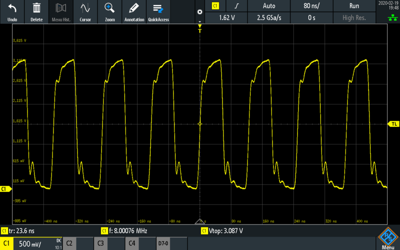
at 8 Mhz. I believe this is the maximum that can be done in this processor clocked at 16 Mhz.
You probably wonder if the analog write in makecode, showin in experiment 2, uses something similar, and the answer is yes. It actually uses the same mechanism, it is implemented in pwmout_api.c in Lancaster University’s mbed-classic repo. The only issue is, the implementation is made to support only microsecond periods.
Remarks
I recently bought a micro:bit, actually for my daughter. I think it is very nice especially with the makecode programming environment, for kids and for beginners.
It was just a coincidence I used a micro:bit for this post, and I also have not used any Nordic Semiconductor development products before. I am very happy for this coincidence because I like their documentation and actually I bought the nRF51 Development Kit as well to use for further experiments. In addition to this, Segger Embedded Studio is free to use with Nordic Semiconductor products and it runs on all platforms, Windows, Linux and macOS. Both micro:bit and nRF51-DK also have J-Link OB, which provides JTAG access without any special equipment. I think if you do not need something more advanced, these products provide a very nice environment, and the best value. Under 50 USD, you have an ARM Cortex-M0 based development board, with JTAG access and with a nice IDE.
This work is licensed under a Creative Commons Attribution-NonCommercial-ShareAlike 4.0 International License.