Demystifying a very simple TrustZone enabled program on ARM Cortex-M33
Introduction
After 10 years or so, I could finally do something with Arm TrustZone technology. TrustZone is available since long but it was a high performance/Cortex-A processor feature, which are used in high-performance embedded devices like smart phones, and because TrustZone is a special security related feature, it is not available to external developers in normal cases in these platforms.
In October 2016, Arm announced they bring TrustZone to new Cortex-M chips (M23 and M33) together with ARMv8-M architecture. Following this, silicon vendors announced MCUs based on these and they are available I think since 2019. At the moment, you can purchase a Cortex-M33 development kit supporting development with TrustZone at a very low-cost for 20 USD for example with NUCLEO-L552ZE-Q. Different evaluation boards exist from ST or other vendors like NXP.
The point of this article is not to explain what TrustZone is and there are also many technical documents explaining everything regarding to TrustZone. The problem I have with all the documentation is that it assumes you gather all information what you need from multiple documents (some of which have exteremely many pages like more than 2000) which are although mentioned as references are not directly inter-linked. So the point of this article is to go through a very simple example (starting with ST’s Getting Started Application Note AN5394 and the example project in STM32CubeL5 MCU Package) and go into detailed explanations when needed. Like a few other posts of mine, I would like this to demystify and be a minimal but complete explanation of what is going on.
I listed all my references at the end of this post. You can click on the tables/diagrams to access the original source material.
Development environment
I am using:
This is basically what you all need (the NUCLEO board I mentioned before is cheaper if you want to purchase one, I am using the Discovery Kit only because I already had it). The discovery kit (like all STM32 based kits I think) includes STLINK which enables you to directly connect the board to the PC through USB and do all flashing and debugging operations. There is no need for a separate Programmer application to flash the program but you need it to make a few configuration changes.
Naturally it is possible to use other IDEs or programming environments but STM32Cube IDE makes it so easy to make something quick, I highly recommend it if you are a beginner.
The very simple example project
I am not giving any program listing here, because it is basically the default TrustZone enabled template provided by STM32CubeL5 MCU Package. The only changes I made is an empty NONSECURE_f() method in NonSecure project, SECURE_f() method (non-secure callable) in Secure project and enabling USART1 in secure context.
A little bit about the software stack
To support development, particularly to support porting software to different architectures, ARM has developed a standard library, called CMSIS.
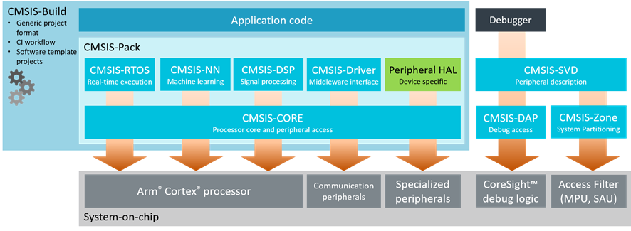
CMSIS
CMSIS, since developed by ARM, naturally is not enough alone to write an executable software since a silicon implementation of a Cortex-M core depends on implementation details. So the silicon vendor (for example ST in my case in this post) also provides some files, then the program can start properly and execute as an application. These are the files like startup_stm32l562qeixq.s, system_stm32l5x.c etc.
In addition to these, silicon vendor may also provide other libraries. In the case of ST, there is a HAL library and LL (Low-Level) library. You can see them in files like stm32l5xx_hal_gpio.c/h and stm32l5xx_ll_gpio.c/h in the projects. It is not a must to use these libraries, but it makes it much easier to make something.
Since HAL/LL is specific to a silicon (or a silicon series), they have to be downloaded accordingly. If you are using, ST32Cube IDE, this is done automatically when you select a device/board when you create a project. If you want to download manually, the one for STM32L5 series is called STM32CubeL5 MCU Package.
Both CMSIS and ST HAL/LL are provided as source codes. You will see all of them as source codes, in your project.
STM32Cube IDE uses the GCC ARM compiler (arm-none-eabi, since there is no OS).
A little bit info about TrustZone
TrustZone controls data accesses and instruction fetches, such that non-secure and secure memory (including peripherals) is isolated.
This isolation is made possible by assigning a security attribute to every memory location. A security attribute can have one of these values:
- Non-secure (NS)
- Secure and Non-secure callable, usually mentioned only as non-secure callable (NSC)
- Secure and not Non-secure callable, usually mentioned only as secure (S)
Probably obvious but this is also the least to the most secure order, so NS > NSC > S.
Access from Core
The security state of processor is the security state of the memory it is executing the code.
- If the code is in NS, the processor is in non-secure state.
- If the code is in S or NSC, the processor is in secure state.
When accessing data:
- if processor is in secure state, it can access data in S, NSC and NS.
- if processor is in non-secure state, it can access data in NS.
All other accesses generate a SecureFault.
When fetching an instruction:
- if processor is in secure state, instruction fetch from S and NSC is possible.
- if processor is in non-secure state, instruction fetch from NS and NSC is possible
In addition, when processor is in non-secure state and it is fetching instruction from NSC, only SG (Secure Gateway) instruction can be executed. Any other instruction and all other accesses generate a SecureFault.
The security attribute of the memory for data access or instruction fetch is based on (fixed) IDAU configuration and (programmable) SAU configuration. The security attribute is the conservative security attribute value of what IDAU and SAU says for the address in question.
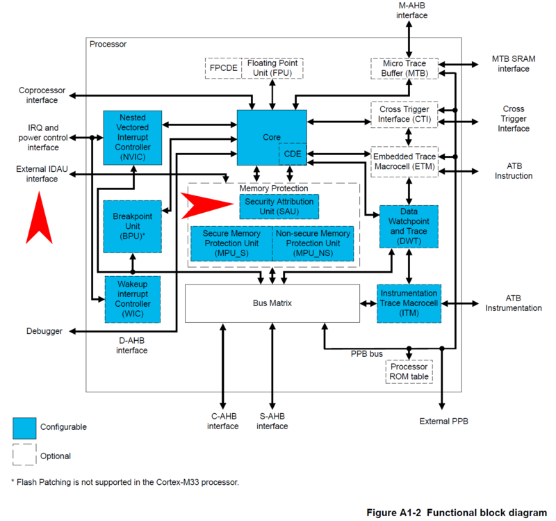
IDAU Interface and SAU in Cortex-M33 Functional Block Diagram
IDAU configuration is fixed by the silicon vendor (so you cannot change this), but you (can/have to) configure SAU.
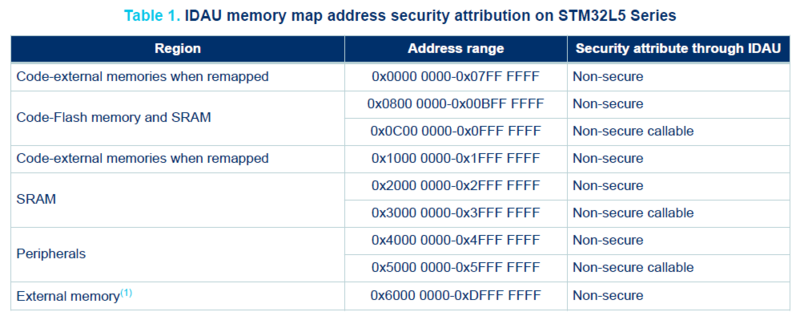
IDAU configuration of STM32L5 series
SAU gives 8 optional and configurable regions in STM32L5, where each region can be set as non-secure (NS) or non-secure callable (NSC). If no SAU region is configured for an address, security attribute is assumed to be secure (S). So if you want to configure a region as non-secure (NS) or non-secure callable (NSC), you have to configure it explicitly.
Access from Peripherals
IDAU and SAU is checked for the accesses from the core (e.g. by the program you have developed) only. From core to peripherals or between the peripherals, mechanisms provided by Global TrustZone Controller is used. More about this later.
Creating a TrustZone enabled project
Enabling TrustZone
TrustZone is not enabled by default on the processor, so the processor can actually be used like a normal processor also. First step is to enable this feature.
There is a single TrustZone Enabled bit (TZEN) for this purpose.
This brings the question where is this bit, because this is a processor state that affects the reset state, it has to be available before reset, so it has to be in a non-volatile area. The answer is that on-chip Flash memory has a section called option bytes for such configuration parameters. When you hear option bytes, it refers to this non-volatile section in Flash. You can use STM32Cube Programmer to modify the option bytes (there are a few more other than TZEN). These are read at reset, and loaded into so-called Flash registers.
The important thing at this point is when you set TZEN, the processor starts at a secure state and Flash and SRAM are all secure by default. This means you cannot run a non-secure code anywhere. You have to mark at least some part of Flash and probably some part of SRAM to be non-secure for non-secure code to be able to run.
The application note exactly mentions for this purpose that you have to configure option bytes as mentioned in the readme.txt in the example project, which is -for the board I am using- at: STM32CubeL5 MCU Package/Projects/STM32L562E-DK/Templates/TrustZoneEnabled/readme.txt.
The readme.txt says we need to configure option bytes as:
- DBANK=1, to enable dual-bank mode of flash
- SECWM1_PSTRT=0x0, SECWM1_PEND=0x7F, to set all pages of Bank1 as secure
- SECWM2_PSTRT=0x1, SECWM2_PEND=0x0, to set none of the pages of Bank2 as secure
It is not as simple as it may sound to explain why these are set as such. This is going to be a big jump but I think it is needed to be known at this point, because I did only realize this later after reading a few other documents. There are multiple units or configurations that makes a memory region or a peripheral to be non-secure or secure. When you are inside the processing core, IDAU (Implementation Defined Attribution Unit, the actual unit is external to the core but it is not relevant since it is used directly by the core) and SAU (Security Attribution Unit) are in effect. When you are outside the core (on the bus or close to the peripheral), GTZC (Global Trust Zone Controller) (and its subunits) is also in effect and furthermore, some devices (so called TrustZone-aware peripherals like Flash) has its own protection mechanisms. So you have to be sure all of these are somewhat aligned to what you are trying to achieve. You may ask why there is a need for GTZC, the reason is IDAU and SAU works only for a program running in the core, but this is not the only way to read/write memory. For example DMA can initiate a transfer between memory or peripherals. Because of this, extra components like GTZC or TrustZone-aware peripherals are needed.
SECWM is Security Watermark, and it is a way to mark Flash regions as secure or non-secure in the Flash (not in IDAU, SAU, GTZC etc.). So no non-secure operation within the system, initiated by core or other peripherals, can reach to a secure region marked like this.
There is no particular reason the watermarks are selected like this. It is only because the linker is configured (through linker descriptions file) in the example according to these values.
It might be a bit hard to see the connection, so let me explain. First, pay attention that these values are in units of Flash pages (hence the name PSTRT/Page-Start and PEND/Page-end) that are to be appended to the base address of corresponding Flash Bank base address. If you check the linker description in non-secure project (STM32L562QEIXQ_FLASH.ld in my case) RAM is set to
ORIGIN = 0x20018000and ROM is set toORIGIN = 0x08040000(I added a zero here before 8 to make it clear it is 0804 not 8040). SECWM2 above is Bank2, and Bank2 starts at0x08040000. When the Flash is used in dual-bank mode (DBANK=1), the page size is 2K.SECWM2_PSTRT=0x1means the security watermark start is at0x08040800whereasSECWM2_PEND=0x0means the last page of security watermark is at0x08040000. As you realize, this does not make sense, the end is before start. This is a way to say there is no secure page in Bank2. On the other hand, SECWM1 settings mark all pages of Bank1 as secure, because 0x7F * 2K pages=256K is the size of Bank1 (half of all Flash which is 512K in this silicon).
If you look at the linker description file in the secure project, RAM is at
ORIGIN = 0x30000000and ROM is atORIGIN = 0x0C000000. What is0x0C000000? In TrustZone architecture, the non-secure and the secure views have different memory views but some addresses are aliases to actual addresses (only a few are not like this, e.g. there are two SysTick, the external memory addresses are not aliased). This means0x08000000in non-secure view is0x0C000000in secure view. So the Bank1 of Flash is at0x0C000000, which is set as secure in security watermark 1 and it is used as ROM in secure project linker configuration.
To sum up, at this point:
- TrustZone is enabled. (TZEN)
- Flash is set to be operated in dual-bank mode. (DBANK)
- Bank1 is set as secure. (SECWM1)
- Bank2 is set as non-secure. (SECWM2)
Creating the Project
Since TrustZone enabled processor runs like a dual-core system (they do not run concurrently but there is a secure code and a non-secure code), actually two outputs (ELF/BIN) are generated. It naturally is easy or maybe only way to have two different projects for each code. When you create a STM32 project in STM32Cube IDE, and check “Enable TrustZone” box, this generates an empty (holder) project and two actual projects under it, one named PROJECTNAME_NonSecure and other named PROJECTNAME_Secure.
You probably wonder, if these projects are compiled in the same way. The answer is almost but not exactly same. There are 2 differences:
- Secure project is compiled with
Secure mode -mcmsesetting checked (Properties > C/C++ Build > Settings > Tool Settings > MCU GCC Compiler > Miscellaneous).- Non-secure project is linked with
secure_nsclib.owhich is an output of Secure project (Properties > C/C++ Build > Settings > Tool Settings > MCU GCC Linker > Miscellaneous).I will explain what these are soon.
You might also wonder if the automatically created or included files in the projects (part of CMSIS and ST HAL) are same. The answer is again almost but not exactly. There are a few differences:
- The NonSecure project, has system_stm32xxx_ns.c file, whereas Secure project has system_stm32xxx_s.c file.
- Secure project has an extra header called partition_stm32xx.h. This header, in addition to a few other things, define the SAU regions.
- Secure Project has an extra source called secure_nsc.c. This is basically provided for implementations of secure_nsc.h which is in a separate folder (neither in NonSecure nor Secure projects).
- Other files like stm32xxx_hal_conf.c/h, stm32xxx_it.c/h and linker descriptions (STM32xxx_FLASH.ld and STM32xxx_RAM.ld) are named the same but their contents are different depending on what you are using in secure and non-secure context.
Function calls
From a software developer perspective, the thing that matter the most is calling functions between secure and non-secure code. The underlying mechanisms are naturally different and quite interesting.
Secure function call (from non-secure)
Secure functions that can be called from non-secure code are also called entry functions, since they provide an entry to secure state.
Normal function calls are implemented with branch instructions. The problem here is, since the point of isolation is for non-secure code to not access secure code freely, the first instruction of the called function can be anything. In order to impose this restriction, an intermediate area called non-secure callable region is created. The only point of this region is to have a hop from non-secure code to secure code.
The mechanism is pretty simple. The non-secure call to secure call is first translated into a branch instruction to non-secure callable code (not directly to the secure code). The first instruction in this code is SG, Secure Gateway. This is the only instruction a non-secure code can fetch and execute in non-secure callable area. Following SG, there is a branch to the actual function in the secure code. Because the link register is modified in the non-secure callable area, the return from secure code goes directly back to non-secure code, the caller.
In order for this mechanism to be transparent, it naturally needs to be implemented by the compiler and linker. Any function marked by CMSE_NS_ENTRY is considered as such a secure function (that can be called by non-secure code) so an entry in non-secure callable area is generated as described above (because of the use of compiler flag -mcmse), and this entry is compiled into secure_nsc.lib mentioned before. That is why secure_nsc.lib is added as an additional object to NonSecure project.
CMSE_NS_ENTRYis defined as__attribute((cmse_nonsecure_entry))for GCC in main.h in Secure project.
A call in non-secure code to a non-secure function (NONSECURE_f) is like this:
.....

08040298 <NONSECURE_f>:
void NONSECURE_f() {
  ...
 8040298:	push	{r7}
 804029a:	add	r7, sp, #0
	__NOP();
 804029c:	nop
}
 804029e:	nop
 80402a0:	mov	sp, r7
 80402a2:	ldr.w	r7, [sp], #4
 80402a6:	bx	lr

.....

80402ec:	bl	8040298 <NONSECURE_f>
So a bl (branch with link) branches to function and function returns with bx (branch and exchange instruction set) lr.
In the case of a call from non-secure code to a secure function (SECURE_f), non-secure code is:
...
08048b08 <__SECURE_f_veneer>:
 8048b08:	push	{r0}
 8048b0a:	ldr	r0, [pc, #8]	; (8048b14 <__SECURE_f_veneer+0xc>)
 8048b0c:	mov	ip, r0
 8048b0e:	pop	{r0}
 8048b10:	bx	ip
 8048b12:	nop
 8048b14:	.word	0x0c03e009

...

 80402f0:	f008 fc0a 	bl	8048b08 <__SECURE_f_veneer>
...
as you see the name, it is not SECURE_f, but SECURE_f_veneer, this is non-secure part of the generated intermediate layer. It basically loads the fixed value 0x0c03e009 to ip (r12) and then branches (bx ip) there. See below for what is in that address.
The secure code is:
...
0c000290 <__acle_se_SECURE_f>:

CMSE_NS_ENTRY void SECURE_f() {
 c000290:	push	{r7}
 c000292:	add	r7, sp, #0
	__NOP();
 c000294:	nop
}
 c000296:	nop
 c000298:	mov	sp, r7
 c00029a:	ldr.w	r7, [sp], #4
 c00029e:	mov	r0, lr
 c0002a0:	mov	r1, lr
 c0002a2:	mov	r2, lr
 c0002a4:	mov	r3, lr
 c0002a6:	vmov.f32	s0, #112	; 0x3f800000  1.0
 c0002aa:	vmov.f32	s1, #112	; 0x3f800000  1.0
 c0002ae:	vmov.f32	s2, #112	; 0x3f800000  1.0
 c0002b2:	vmov.f32	s3, #112	; 0x3f800000  1.0
 c0002b6:	vmov.f32	s4, #112	; 0x3f800000  1.0
 c0002ba:	vmov.f32	s5, #112	; 0x3f800000  1.0
 c0002be:	vmov.f32	s6, #112	; 0x3f800000  1.0
 c0002c2:	vmov.f32	s7, #112	; 0x3f800000  1.0
 c0002c6:	vmov.f32	s8, #112	; 0x3f800000  1.0
 c0002ca:	vmov.f32	s9, #112	; 0x3f800000  1.0
 c0002ce:	vmov.f32	s10, #112	; 0x3f800000  1.0
 c0002d2:	vmov.f32	s11, #112	; 0x3f800000  1.0
 c0002d6:	vmov.f32	s12, #112	; 0x3f800000  1.0
 c0002da:	vmov.f32	s13, #112	; 0x3f800000  1.0
 c0002de:	vmov.f32	s14, #112	; 0x3f800000  1.0
 c0002e2:	vmov.f32	s15, #112	; 0x3f800000  1.0
 c0002e6:	msr	CPSR_fs, lr
 c0002ea:	push	{r4}
 c0002ec:	vmrs	ip, fpscr
 c0002f0:	movw	r4, #65376	; 0xff60
 c0002f4:	movt	r4, #4095	; 0xfff
 c0002f8:	and.w	ip, ip, r4
 c0002fc:	vmsr	fpscr, ip
 c000300:	pop	{r4}
 c000302:	mov	ip, lr
 c000304:	bxns	lr
...

...
Disassembly of section .gnu.sgstubs:
...
0c03e008 <SECURE_f>:
 c03e008:	sg
 c03e00c:	b.w	c000290 <__acle_se_SECURE_f>
...
First you can see the actual SECURE_f method is renamed to __acle_se_SECURE_f and the non-secure callable entry is named SECURE_f which is at 0x0c03e008. So why the branch before was to 0x0c03e009. It is because the bit[0] of the register in bx instruction identifies the instruction set and it has to be 1 for Thumb state. So the code before is actually branching to 0x0c03e008, so SECURE_f above. The first instruction is sg (secure gateway), it does nothing other than switching the security state to secure since it is in secure memory (remember non-secure callable is secure). The second is a 32-bit branch, b.w to actual code of the function SECURE_f. None of the branches until now since the first one in non-secure code (80402f0: f008 fc0a bl 8048b08 <__SECURE_f_veneer>) saves the next address to lr, so the return from actual SECURE_f implementation (__acle_se_SECURE_f), the last instruction bxns lr causes the execution to branch to address stored in lr and particularly this branch goes to a non-secure code.
It is probably obvious now but if we look at the linker description in Secure project, we can see where .gnu.sgstubs section is placed:
...

  ROM_NSC	(rx)	: ORIGIN = 0x0C03E000,	LENGTH = 8K    /* Non-Secure Call-able region */

...

  .gnu.sgstubs :
  {
    . = ALIGN(4);
    *(.gnu.sgstubs*)   /* Secure Gateway stubs */
    . = ALIGN(4);
  } >ROM_NSC

...
as expected it is placed into the non-secure callable region at ORIGIN = 0x0C03E000.
Here is a nice official diagram for entry function:
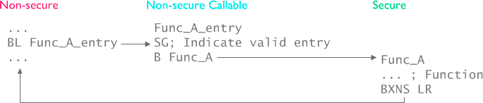
Secure function call
Non-secure function call (from secure)
There is no access issue from secure to non-secure, however the security state has to be switched and the register values etc. of secure state should not be leaked to non-secure state. Because of this, non-secure function call also has a special treatment.
The non-secure function is defined and implemented not differently in non-secure code.
The non-secure function prototype is marked with CMSE_NS_CALL in secure code. This special indication creates stubs necessary to switch security state to non-secure when branching (using BLXNS instead of B instruction) and sanitizing the registers.
I have a feeling that non-secure function calls are thought to be more rare than secure function calls. There is no direct mechanism to write such methods (in the sense of secure_nsc.lib above), so how a non-secure function is known by the secure code is up to the application programmer. I used a simple secure method to send the function pointer to secure code similar to the existing fault callback register methods.
Here is the non-secure function:
void NONSECURE_f() {
 8040298:	push	{r7}
 804029a:	add	r7, sp, #0
	__NOP();
 804029c:	nop
}
 804029e:	nop
 80402a0:	mov	sp, r7
 80402a2:	ldr.w	r7, [sp], #4
 80402a6:	bx	lr
The call from secure code is like this:
	pNONSECURE_f();
 c0005c8:	ldr	r3, [pc, #204]	; (c000698 <__acle_se_SECURE_f+0xf4>)
 c0005ca:	ldr	r3, [r3, #0]
 c0005cc:	mov	r4, r3
 c0005ce:	lsrs	r4, r4, #1
 c0005d0:	lsls	r4, r4, #1
 c0005d2:	mov	r0, r4
 c0005d4:	mov	r1, r4
 c0005d6:	mov	r2, r4
 c0005d8:	mov	r3, r4
 c0005da:	vldr	s0, [pc, #192]	; c00069c <__acle_se_SECURE_f+0xf8>
 c0005de:	vldr	s1, [pc, #188]	; c00069c <__acle_se_SECURE_f+0xf8>
 c0005e2:	vldr	s2, [pc, #184]	; c00069c <__acle_se_SECURE_f+0xf8>
 c0005e6:	vldr	s3, [pc, #180]	; c00069c <__acle_se_SECURE_f+0xf8>
 c0005ea:	vldr	s4, [pc, #176]	; c00069c <__acle_se_SECURE_f+0xf8>
 c0005ee:	vldr	s5, [pc, #172]	; c00069c <__acle_se_SECURE_f+0xf8>
 c0005f2:	vldr	s6, [pc, #168]	; c00069c <__acle_se_SECURE_f+0xf8>
 c0005f6:	vldr	s7, [pc, #164]	; c00069c <__acle_se_SECURE_f+0xf8>
 c0005fa:	vldr	s8, [pc, #160]	; c00069c <__acle_se_SECURE_f+0xf8>
 c0005fe:	vldr	s9, [pc, #156]	; c00069c <__acle_se_SECURE_f+0xf8>
 c000602:	vldr	s10, [pc, #152]	; c00069c <__acle_se_SECURE_f+0xf8>
 c000606:	vldr	s11, [pc, #148]	; c00069c <__acle_se_SECURE_f+0xf8>
 c00060a:	vldr	s12, [pc, #144]	; c00069c <__acle_se_SECURE_f+0xf8>
 c00060e:	vldr	s13, [pc, #140]	; c00069c <__acle_se_SECURE_f+0xf8>
 c000612:	vldr	s14, [pc, #136]	; c00069c <__acle_se_SECURE_f+0xf8>
 c000616:	vldr	s15, [pc, #132]	; c00069c <__acle_se_SECURE_f+0xf8>
 c00061a:	bl	c000234 <__gnu_cmse_nonsecure_call>
As you see there is a bl instruction to so called __gnu_cmse_nonsecure_call, which is:
0c000234 <__gnu_cmse_nonsecure_call>:
 c000234:	stmdb	sp!, {r5, r6, r7, r8, r9, sl, fp, lr}
 c000238:	mov	r7, r4
 c00023a:	mov	r8, r4
 c00023c:	mov	r9, r4
 c00023e:	mov	sl, r4
 c000240:	mov	fp, r4
 c000242:	mov	ip, r4
 c000244:	vpush	{d8-d15}
 c000248:	mov.w	r5, #0
 c00024c:	vmov	d8, r5, r5
 c000250:	vmov	s18, s19, r5, r5
 c000254:	vmov	s20, s21, r5, r5
 c000258:	vmov	s22, s23, r5, r5
 c00025c:	vmov	s24, s25, r5, r5
 c000260:	vmov	s26, s27, r5, r5
 c000264:	vmov	s28, s29, r5, r5
 c000268:	vmov	s30, s31, r5, r5
 c00026c:	vmrs	r5, fpscr
 c000270:	movw	r6, #65376	; 0xff60
 c000274:	movt	r6, #4095	; 0xfff
 c00027e:	msr	CPSR_f, r4
 c000282:	mov	r5, r4
 c000284:	mov	r6, r4
 c000286:	blxns	r4
 c000288:	vpop	{d8-d15}
 c00028c:	ldmia.w	sp!, {r5, r6, r7, r8, r9, sl, fp, pc}
here is the BLXNS instruction, which switches to non-secure state and branches to NONSECURE_f() in non-secure code.
Here is the nice official diagram for non-secure call:
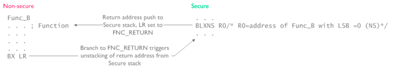
Non-secure function call
There is something interesting here when returning from the non-secure function. Because the return address is stored in secure stack, and non-secure stack is different, a special value FNC_RETURN is used as LR, which causes switching the security state and returning back.
Boot address
From the code perspective above, all is fine, but where does the processor start executing or boot ?
The boot address is based on different things, and for TZEN=1, they are: BOOT_LOCK, nSWBOOT0, depending on nSWBOOT0 either nBOOT0 or BOOT0 pin PH3 and RSS command. In my case, and it is the simplest TrustZone config, BOOT_LOCK = 0, nSWBOOT0 = 1, BOOT0 pin PH3 = 0, so SECBOOTADD0 defines the boot address.
Since TZEN=1, the processor starts at secure state, so the boot address has to be in a secure region. In my example, this address is 0x0C000000 since Secure project ROM section is defined to start at that address. The SECBOOTADD0 contains the value 0x18000 which is again in 2K pages, so 0x18000 * 2K = 0x0C00000.
This is the default value of SECBOOTADD0 so I did not program this.
This is actually not the full story. ARM v8-M core actually starts at what Secure Vector Table Offset Register (VTOR_S) specifies. This flash option byte, SECBOOTADD0, I believe provide the default value for VTOR_S.
Program flow
Since the processor starts in secure state when TrustZone is enabled, first, secure code starts. This code, after initialization, starts non-secure code and this does not return. Basically this typically means there can be an infinite loop in non-secure code like programs in TrustZone disabled apps, but secure code consists of functions that are called either from non-secure area or from other functions in secure area.
Non-secure callable functions
The default template provides secure_nsc.h for non-secure callable entry definitions and secure_nsc.c for their implementations. There is one function that is not visible here and it is SECURE_SystemCoreClockUpdate. It is called from non-secure SystemCoreClockUpdate as well.
Peripherals
Like memory regions, each peripheral has to be in one of these contexts, secure or non-secure. Secure peripherals cannot be accessed by a non-secure code.
Some peripherals, like GPIO, are TrustZone aware, meaning they implement TrustZone behavior on their own, thus they are connected to the bus directly. For example, each GPIO pin can be configured as secure or non-secure with its SECCFGR register.
Other peripherals, like SRAM or UART, are not TrustZone aware, but functions within Global TrustZone framework and its TrustZone functionality is controlled by Global Trust Zone Controller (GTZC). For example, for SRAM, GTZC provides block-based memory protection controller (MPCBB) to control the security states of blocks (256-byte pages) of associated SRAM. Other peripherals, such as UART, can be always secure, always non-secure or securable (by configurable properties), that is configured by TrustZone Security Controller (TZSC).
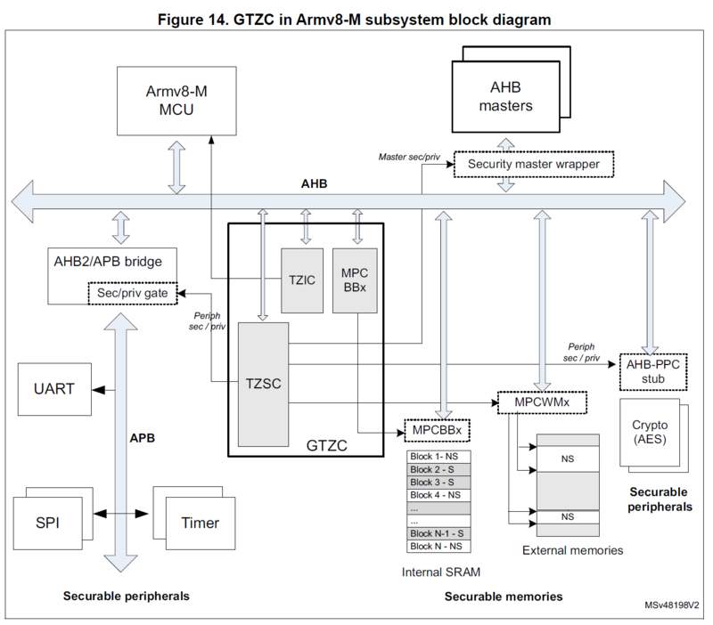
Global TrustZone Controller
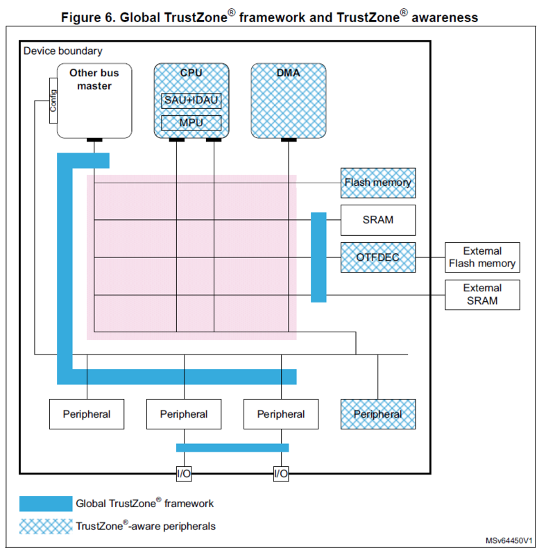
Global TrustZone Framework
As an example, if USART1 is enabled in secure context, following code is automatically added to MX_GTZC_Init in secure code:
HAL_GTZC_TZSC_ConfigPeriphAttributes(GTZC_PERIPH_USART1, GTZC_TZSC_PERIPH_SEC|GTZC_TZSC_PERIPH_NPRIV)
this configures USART1 as a secure and not privileged peripheral, and this is enforced by TZSC.
There is one more component of GTZC, it is called TrustZone Illegal Access Controller (TZIC). It basically gathers all illegal access events from the system and generates a single interrupt directly going to NVIC.
Summary
TrustZone is enabled, Flash security watermarks are set and SECBOOTADD0 are programmed as Flash option bytes.
NonSecure and Secure code is developed in different projects. Secure code runs first, which runs non-secure code, which probably calls secure code time to time.
Secure functions that can be called from non-secure code are marked and an intermediate code (secure gateway stubs) compiled into a library which is used by a non-secure code during compilation/link and also put into non-secure callable region.
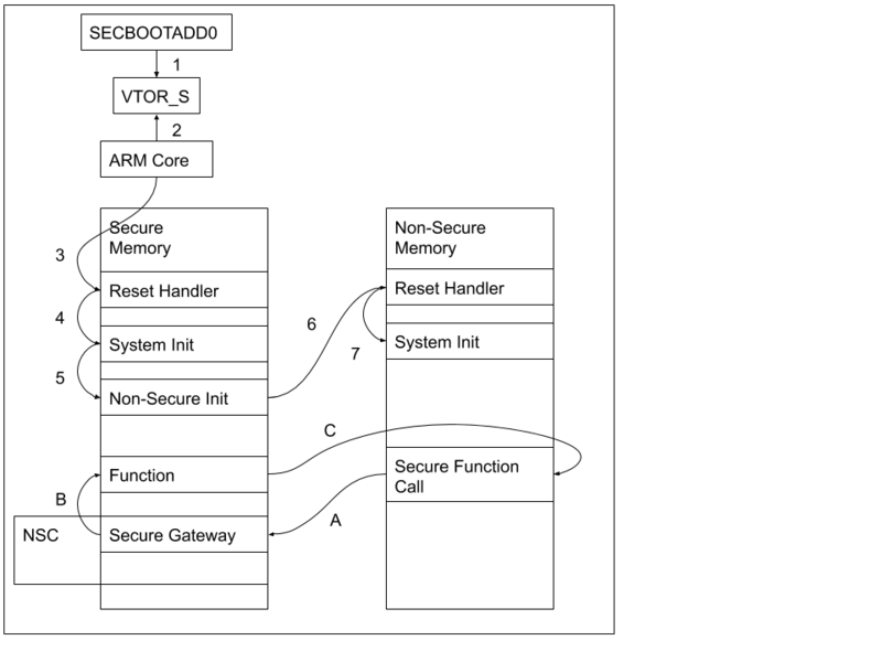
Simplified execution flow from reset (1-7) and secure function call (A-C)
References
AN5394: Getting started with projects based on the STM32L5 Series in STM32CubeIDE
AN5347: STM32L5 Series TrustZone features
RM0438: Reference manual: STM32L552xx and STM32L562xx advanced Arm-based 32-bit MCUs
Arm v8-M Security Extensions: Requirements on Development Tools
This work is licensed under a Creative Commons Attribution-NonCommercial-ShareAlike 4.0 International License.