Z0 Probe
Entry level oscilloscopes (with up to 500Mhz bandwidth or so) usually come with passive (high R, normal C) probes. Above 500Mhz, I thought you always need an active (high R, low C) probe. I just learned there is also something called a Z0 probe with a pure low resistive load (C is only due to parasitic capacitance). This probe is used when a very high bandwidth is required (e.g. 8 GHz), and it is quite suitable for probing digital circuits (because they do not need a probe with a high impedance like passive or active probes). This probe construction is not new, it is mentioned at least in one Tektronix document from 60s. There are also examples and good explanations on the internet for Z0 probes.
Z0 probe is called by different names, resistive probe, low-impedance probe, or for example Rohde & Schwarz calls it Passive Broadband Probes. I will come back to Rohde & Schwarz’s description at the end of the post.
I decided to test this probe construction since it is very simple to make, and compare it in my oscilloscope (Rohde & Schwarz RTB2004) with the passive probes I have (RT-ZP03). Both the oscilloscope and the passive probe have 300MHz bandwidth.
I purchased a RG174/U coax cable and a Vishay CMF 453 Ohm resistor. Since the cable has 50 Ohm impedance, 453 Ohm gives almost 10:1 factor like commercial probes. I soldered the resistor to the center connector in series (hidden under the red tape on the photo below), and it becomes the probe tip. I also soldered a solid wire to the shield to provide the ground tip. There are much better constructions in internet (using SMD resistors etc.) you can easily find, this is just my first try. Also, it is usually said that you should be careful with your resistor choice because of high frequency use, I selected Vishay CMF because it is mentioned to have excellent high frequency characteristics but I am also not 100% sure if it is 100% suitable.
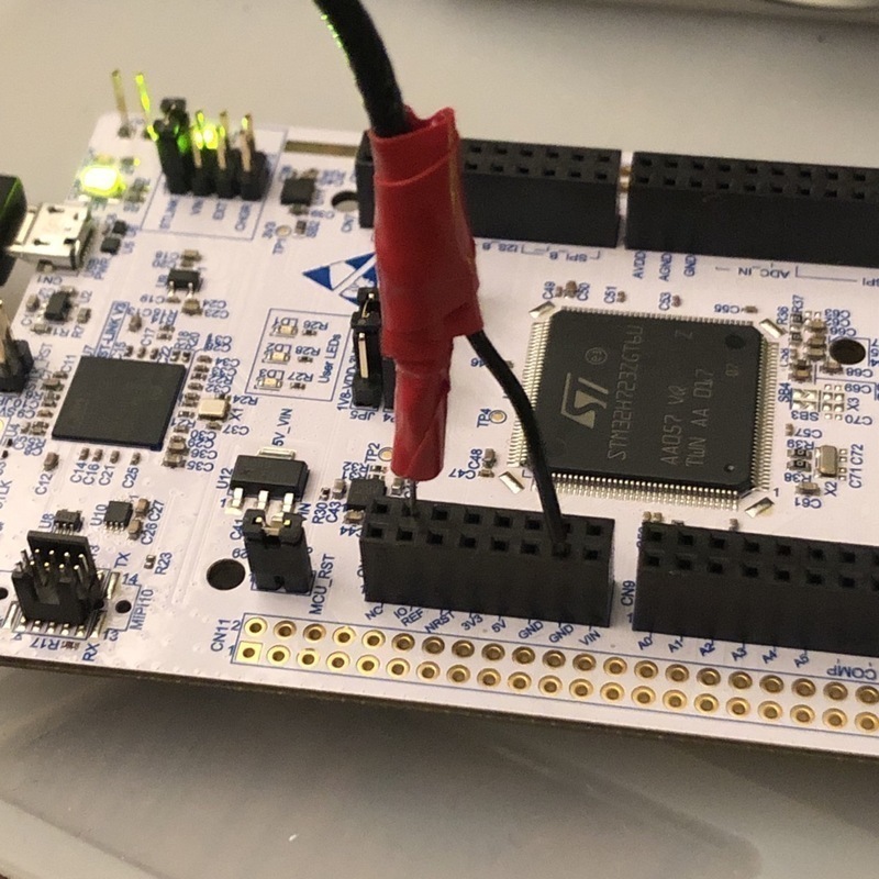
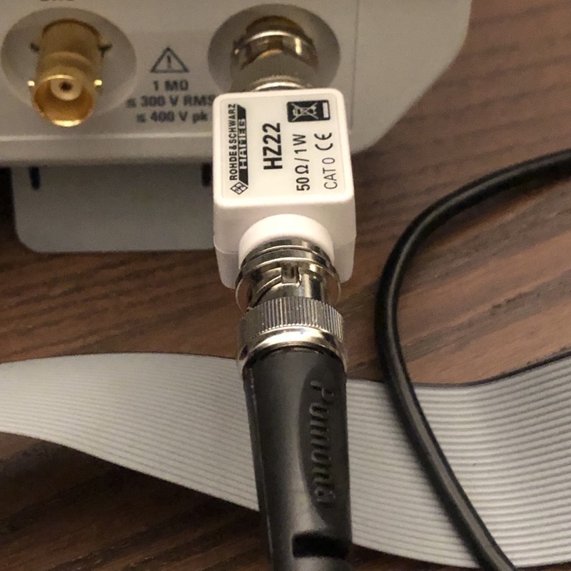
This probe requires 50 Ohm termination at the oscilloscope. Since I only have 1 MOhm, I am using an external 50 Ohm termination.
I am not sure what to expect from this on my oscilloscope, because many examples on the internet uses such a probe for signals around 1 Ghz, I believe its benefits are much more visible then, but my oscilloscope has 300 Mhz bandwidth. Anyway, I measured 55, 110 and 275 MHz signals, taken from STM32H7 MCO2 output.
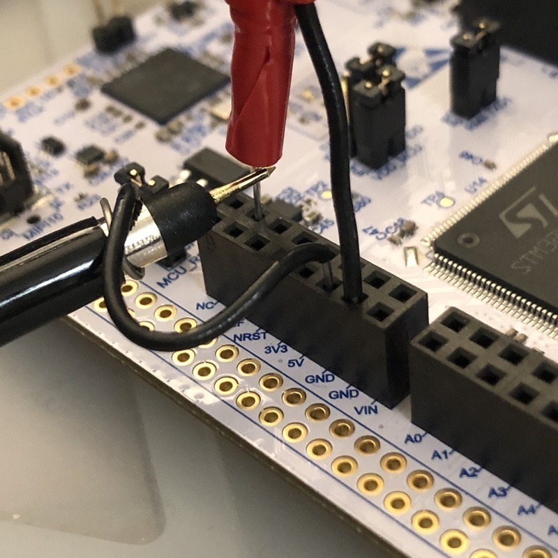
For the passive probe, because it is better to make the ground connection as short as possible, and to make this comparison more meaningful, I removed the ground cable with the clip and using just a short wire.
Here are the results from the passive probe (RT-ZP03 300Mhz):
55 Mhz looks OK to me.
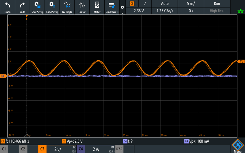
110 Mhz displays only the main frequency component so it became a sinusoidal. The amplitude decreased to 2.5V, this was something I was not expecting but it is not strange. Because the passive probe specification of 10 MOhm is only for low frequency, having 10 MOhm resistance and 12pF capacitance, the passive probe has only around 120 Ohm impedance at 110 Mhz. This is lower than Z0 probe.
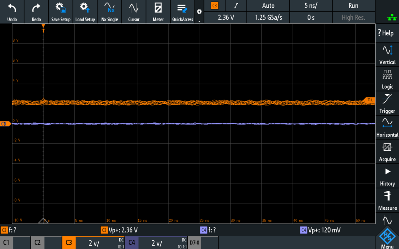
This results with 275 Mhz input is something maybe not surprising since it is very close to full bandwidth but it is naturally strange.
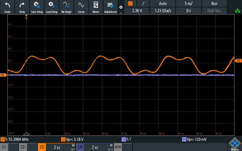
Now lets look at the results with Z0 probe:
55 Mhz looks OK like the passive probe, maybe even better.
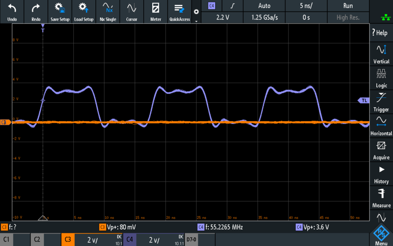
110 Mhz looks better than the passive probe, in the sense the other harmonic is also visible. I think, and speculating, this is because Z0 probe has a higher bandwidth than the oscilloscope so this result is showing mainly the limitation of the oscilloscope, whereas the result with the passive probe was showing either mainly the probes limitation or the limitation of the probe-oscilloscope system.
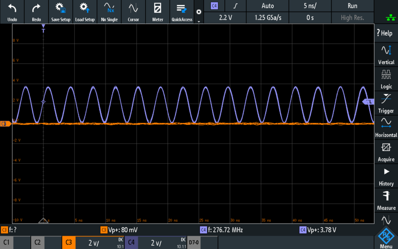
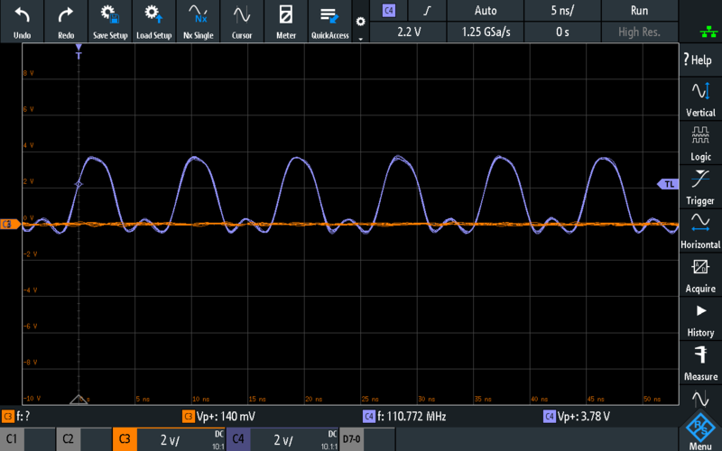
This result with 275 Mhz signal is very nice comparing to the passive probe. The signal is clearly still visible.
Maybe also the best thing is if you pay attention to the signal amplitude, it is more or less same for all measurements. This is because Z0 probe is resistive (until the effects of parasitic capacitance become visible), it loads the circuit the same, or in other words, it has a high bandwidth and its impedance also does not change like the passive probe.
So I guess it is safe to say Z0 probe might be useful even with an entry level oscilloscope having a 300 Mhz bandwidth.
Looking at the Rohde & Schwarz Passive Broadband Probes page, they are described clearly (and matching the results I have even obtained for this post):
- high bandwidth (8 Ghz)
- extremely low input capacitance (0.3 pF)
- purely passive, their impedance is low and stays constant over its entire frequency range
- economical alternative (but it still costs I think over 2000 USD) to active probes (which are even more expensive) to be used in high-speed digital circuits
Of course something you make at home cannot have a bandwidth like 8 Ghz, but it seems 1 Ghz is quite possible looking at the examples on internet. It is a very simple and interesting project, so I definitely recommend you to try.
Here are some resources:
This work is licensed under a Creative Commons Attribution-NonCommercial-ShareAlike 4.0 International License.