Work-In-Progress: Studying Ethernet Physical Layer 1
A fresh start to 2023, I try something new and publish a work in progress. I am going to update, probably rewrite this post a few times and eventually remove Work-In-Progress from the title. I also update the date of this post, RSS subscribers may get an update notification.
Introduction
Many people know about Ethernet Layer 3 and above (that covers IP, TCP, UDP). Many power users or people working in software development or system/network administration know a lot about Ethernet Layers up to and including Layer 2 (which covers MAC). However, I think it is pretty rare to know about Ethernet Physical Layer 1 unless you are actively working on a particular ethernet related hardware. This was also the case for me and I pose myself a challenge to learn about it.
Rather than a normative text, I try to write this post as my journey on this study, but naturally it was not as linear as this text. So the concepts may look like out of order sometimes.
Scope
IEEE 802.3-2018 Ethernet spec has 5600 pages. It starts from 10Mb/s (which I barely remember using) to 400Gb/s. Because it is very similar to Gigabit Ethernet (1000Base-T), it is supported almost everywhere and it requires the least amount of resources, I chose to work with 100Base-TX, that is using twisted-pair copper cables (CAT) at 100Mb/s speed. 10Base-TX at 10Mb/s is even simpler, but I find it too different, so I decided on 100Base-TX.
Also, I decided to work only on RX signals. This is not important for this study, as RX and TX carry same information.
I also omit the auto-negotiation process. You will also see later that I disable low power idle state or energy efficient ethernet.
So the scope is, passively capturing the RX signals (RX+ and RX-) of an already negotiated 100Base-TX transmission and decoding this in software.
Extension to 1000Base-T
How easily can this study be extended to 1000Base-T ?
100Base-T uses (a different) one pair per receive and transmit (each pair has one direction, RX or TX). It uses 4B5B with MLT-3 signalling at 125MBd symbol rate having 31.25MHz bandwidth. It can work with a cable having 100MHz bandwidth.
1000Base-T uses (the same) 4 pairs per receive and transmit (the 4 pairs are bidirectional). It uses TCM with 4D-PAM5 signalling at 125MBd symbol rate having 62.5MHz bandwidth. It can also work with a cable having 100MHz bandwidth.
The obvious differences are:
There is a need for sampling of four pairs in 1000Base-TX.
It uses Trellis coded modulation (TCM) and 4D-PAM5 signalling rather than 4B5B and MLT-3.
They look similar but also different and everytime I look at 1000Base-T standard, it looks more complicated than I thought. I am not sure how easy it would be to extend this study to 1000Base-TX.
Unknowns
There is probably no need for equalization since in lab/desk conditions I am using a shortest possible cable, so the cable distortion should be minimal.
I do not know if I need to implement anything for timing/clock recovery and baseline wander correction.
Equipment
It is not very straightforward what is needed for this study without spending a fortune. Industry standard ethernet compliance kits and oscilloscopes with ethernet protocol decoders are extremely expensive, and if everything is done automatically where is the fun.
At the moment, I am using minimally the following:
- PC Engines apu4d4 System Board, using as packet generator
- Winford Diagnostic Breakout Switch Board with RJ45 Connectors
- Keysight MSOX6004A Oscilloscope (2.5GHz) with 2x N2894A Passive Probes (700MHz) and dual-lead adapters
- My PC, running Ubuntu 22.04, for software
MSOX6004A is connected to my lab network with its LAN interface which I use for programming through socket 5025.
I also have the following for using a PHY with RMII signals (it was something I was planning to do at some point in the past):
- Waveshare LAN8720 ETH Board, which has a PHY converting Layer 1 to MAC RMII
- R&S NGE100 Power Supply, for powering the ETH Board
- Digilent PMOD TPH2, to help with probing
- A small protoboard with a few male headers for ground connections
- Digilent Digital Discovery and its High Speed Adapter to capture RMII signals
- An FPGA dev board, maybe to use RMII directly to make a packet generator
I also have a HP 1920 Gigabit Switch which I can use to observe actual traffic as it supports port mirroring.
Setup
At the moment, I am following this approach. I will probe the ethernet signals (RX only) on the wire, capture them and decode on PC with a software I will write. This is effectively what a PHY integrated circuit does in real-time.
Setup
Packet Generator
A controlled traffic/ethernet packet generator is not very difficult. I am using apu4d4, and either by using existing utilities in Linux, or using TRex, or writing a code I can send various packets in a controlled fashion.
Another alternative would be to connect the LAN8720 to an FPGA for transmit and use this as a packet generator. This would be absolutely controlled system as there is no software, the timing of the packets I think would be made as close to perfect as required. I keep this in mind.
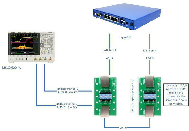
apu4d4 is connected to Breakout Switch Board in loopback (apu4d4 port 3 is connected to port 4). I use two such boards connected back to back with an ethernet cable, because I may need more test/probe points. One breakout switch board has two sets of test points for all 8 lines (of RJ45) plus the connector grounding.
As I said above, 100Base-TX requires only 2 pairs of lines (4 in total), meaning 2 lines for receive (RX) and 2 lines for transmit (TX).
Differential Signalling
Why 2 lines for RX ? It is because ethernet uses differential signalling (as at the moment all modern high speed systems). Differential signalling means there is a positive and negative signal carrying the same information and this improves electrical characteristics of the transmission. Actually the information should be retrieved not from the positive or negative signals, but from the difference (positive - negative) of them, hence the name differential. So the differential signals can be said to be self-referenced, there is no ground or reference point.
The problem is, almost all test equipments, oscilloscopes, logic analyzers or digitizers, has only single-ended inputs, so the probe is connected to signal and both probe and the signal has the same reference. Probing a differential signal is possible only two ways:
using a differential probe: this is the best way, the problem is differential probes are very expensive.
using math: not as effective as differential probe, but because I am not doing something complicated this is enough. It simply means to capture positive and negative signal to the same reference at the same time, and subtract them, and use the subtraction result as the differential signal. A disadvantage is you have to use 2 channels for 1 differential signal.
Using the Breakout Switch Board, I connect RJ45 pin 3 (RX+) to analog channel 1 and RJ45 pin 6 (RX-) connected to analog channel 2 of the oscilloscope, and a math channel M1 is configured for subtracting analog channel 2 from analog channel 1.
Restricting Negotiation to 100Base-TX
Both apu4d4 and HP 1920 supports 1000Base-T so they naturally negotiate to this speed if not explcitily restricted. Because the breakout switch board has switches to disconnect certain lines, an easier way to limit speed to 100Base-TX, is to make it a 2 pairs cable, connecting only 1-2 and 3-6 pairs and disconnecting others. So I do this, and as expected it works as expected.
Capturing
There are a few different ways of capturing these signals, each with different pros and cons. At the moment I am using the first alternative below, capturing the analog channels at 500 MegaSamples per second (MS/s). Why 500MS/s ? I do not have a reference. I definitely do want to sample exactly at 125MS/s and also not more than 1GS/s. Although it is a hardware implementation, Andrew Zonenberg in his TRAGICLASER 100Base-TX implementation on an FPGA used 500MS/s with success, so I decided to use this rate as well.
Capturing RX+ at analog channel 1 and RX- at analog channel 3
This is exactly what happens inside a real PHY. The ethernet signal goes to ADC initially, probably a diffrential ADC. LAN8720 spec. says it has a 6-bit ADC running at 125 MegaSamples/s (MS/s). It can run at 125MS/s because it can use different phases of its clock, meaning it can adjust the point it samples. As I am not going to do this in capturing, I need to use a higher rate.
My scope, MSOX6004A, has 8-bit ADC and can sample 2 channels at up to 20GS/s. This is good but there is a problem. PHY runs in real-time in hardware (meaning it does not need to store many bits, probably only a few), but I need to capture a portion of the signal, at least including one or two packats. This means capture needs memory. MSOX6004A has 4Mpoints memory (when only two interleaved channels are used, hence the reason for using analog channels 1 and 3 not 1 and 2). This means at 20GS/s, memory is exhausted in 200us.
100Base-TX signalling rate (or line rate) is 125Mbps (because of 4B5B code applied to 100Mbps data). This means there is a symbol-bit (code in ethernet terminology) every 8 ns.
Then, 200us would mean, (1000/8 bits/us) x 200us = 25000 symbol-bits.
At 500MS/s a total length of 8ms can be captured. This is not much for certain things but long enough.
The captured signals can then be subtracted in software to get the actual differential signal.
Capturing the function/math channel of subtraction
This is same as above but instead of capturing two signals, calculating the difference can be done in the scope and only this calculated math channel can be transferred to the PC. I do not think this would cause any loss of precision but I did not check. It is not that important anyway, downloading the capture of a single channel is pretty fast. So there is actually no need to do this. Math channel can still be used for display purposes when needed.
Capturing the digital channels
I did not realize this is possible at first, because I was thinking the threshold for digital channels have to be positive, and the ethernet signal is not only positive. Then I realized it is actually possible to use a negative threshold on the scope. However, the threshold can only be set to pods (groups of digital channels). On my scope, I have two pods, and it works for 100Base-TX, because 100Base-TX uses MLT-3 signalling which has signal levels of 1V, 0 and -1V (this is the differential signal, RX+ and RX- has half of this value). So if pod 1 threshold is set to for example 250mV, and pod 2 to -250mV, and then connecting digital channel 0 (of pod 1) to RX+ and digital channel 8 (of pod 2) also to RX+ forms a 2-bit bus identifying the 3 states. 11 is + state, 01 is 0 state and 00 is -1 state, where 10 cannot happen.
This is an interesting approach as there are more digital channels then analog channels in a scope, and actually a logic analyzer can be used instead of a scope.
One problem is trigger threshold accuracy is approx. +-100mV, so it can be a problem. Another restriction is digital channels are sampled at max. 1GS/s.
Not a restriction with the scope but with a logic analyzer (like digital discovery), there can be a problem because negative threshold may not be available.
Using a line receiver and then capturing digital channels
This is similar to above but rather than using digital channels directly, a pair of line receiver ICs can be connected to ethernet lines and then the output (at LVCMOS levels) can be directly used by digital channels without negative thresholds.
The benefit of this would be to be able to use a logic analyzer like digital discovery which has I think 256M samples memory when only 8 channels are used.
This sounds good for implementing a PHY, but I am not sure if actual lines can be tapped like this, this requires more thoughts on hardware.
Decoding
Decoding of quantized (digitally captured) analog RX+ and RX- signals are purely done in software offline. I am not interested in real-time performance for this post so it is not very important how fast this can be done, so I am using Python. The only important thing is there has to be enough data sampled at an enough sample rate for decoding to be successful. Hence, capturing has a direct impact.
100Base-TX Ethernet Signal and MLT-3
Here is a capture of 100Base-TX signal on the wire:
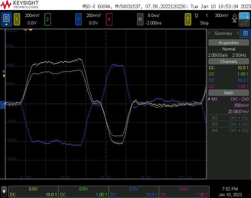
a randomly captured 100Base-TX 4B5B MLT-3 signal
This signal does not mean anything, it just clearly shows the MLT-3 encoded signal. MLT means Multi-Level Transmit, and 3 means it has 3 levels, +, 0 and -.
Channel 1 in yellow shows RX+. Channel 3 in blue shows RX-. These are the differential pair, hence they are symmetrical around 0.
Math channel 1 in pink shows the differential signal (RX+ minus RX-). The scale of math channel is 500mV/div whereas it is 200mV/div for channels.
The signal levels on ethernet wire are 1V peak-to-peak, that is from 500mV to -500mV, so it is a very low voltage. When the differential signal is taken, this is doubled, so from 1V to -1V.
On purpose, I set the time scale to 8ns/div. So each division is actually one bit on the line. You can see it starts with 0, then stays +1 for 3 time units, then goes to 0, then goes to -1, and then stays again at 0 until the end.
MLT-3 Encoding does not directly translated to ones and zeroes. Instead, it encodes the transitions. Whenever 1 is to be encoded, the state of MLT-3 changes from 0 to 1, 1 to 0, 0 to -1, -1 to 0 etc. Whenever 0 is to be encoded, the state is not changed. So above, each transition encodes a one, whereas each non-transition encodes a zero.
What is IDLE on the wire ? and Energy Efficient Ethernet (EEE)
100Base-TX (this is different than 10Base-TX but similar to 1000Base-T) does not keep the line unchanged when there is nothing to transmit. Instead, it transfers IDLE symbol. This is to keep the line and the receiver active. At least this was what I read. However, when I look at the wire, I see something different.
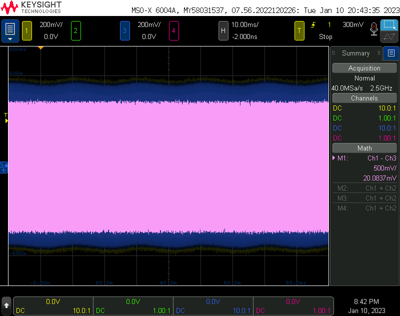
The figure below is captured when the transmission was idle, there is nothing transferred on the wire.
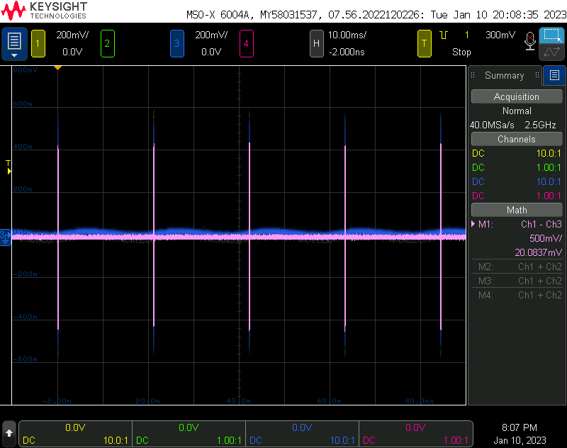
RX signal when the transmission was idle
There are three things here that I was not expecting:
- The line really stays at zero level mostly
- There is something periodic going on, every 20ms or so.
- There is a slight wandering (DC offset change) on individual parts of differential signal lines but the differential signal itself (as expected) has no DC.
The last one is not much important for me at least, but first two requires investigation. Which brings me to Energy Efficient Ethernet (EEE).
I was totally unaware of this until yesterday (2023-01-09). I maybe heard the term but I did not know what it is. Yesterday, when probing the wire, I realized this, the line was going down to zero when idle, and then there are some periodic bursts. So I read about it.
As it can be seen, Energy Efficient Ethernet makes the transmitter takes the line to zero levels when there is no activity, but in order to keep things still in sync, it sends a refresh signal periodically. The details are different for each ethernet version, and for 100Base-TX (source IEEE 802.3-2018 Table 78.2):
Ts: the period of time that the PHY transmits the sleep signal before turning all transmitters off is minimum 200us, maximum 220us.
Tq: The period of time that the PHY remains quiet before sending the refresh signal is minimum 20000us (20ms), maximum 22000us (22ms).
Tr: duration of the refresh signal is minimum 200us, maximum 220 us.
Now it totally makes sense. What is seen here are refresh signals, around every 22ms. Refresh signal is also around 220us, see below.
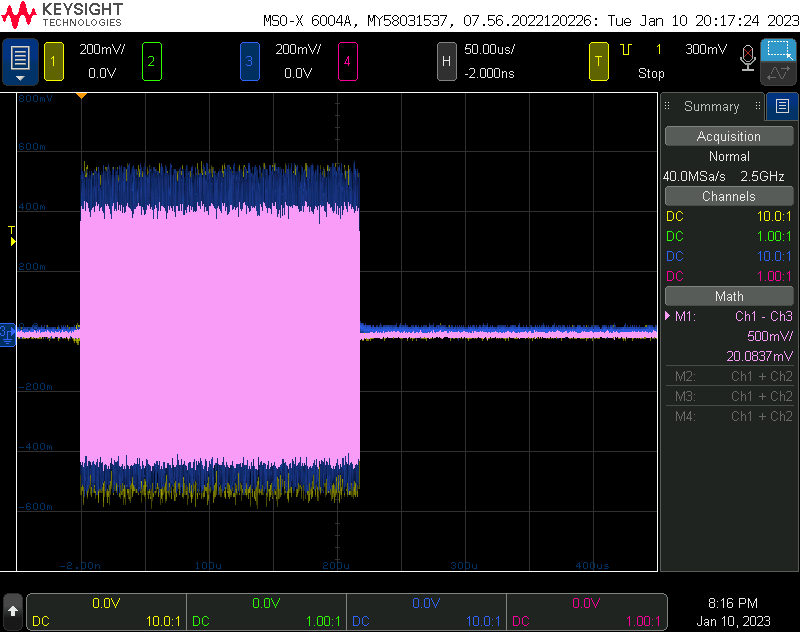
EEE refresh signal
Here how it is shown on the standard, LPI means Low Power Idle:
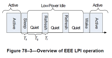
(source: IEEE 802.3-2018)
The sleep signal and the refresh signal consists of SLEEP code-group which is 00000. What this means will be clear later.
What is IDLE on the wire ? without Energy Efficient Ethernet (EEE)
EEE is certainly a nice thing but unnecessarily complicates this study at least now. So I would like to disable it, and also want to see the idling line without EEE.
EEE state can be queried and modified (turned off and on) with ethtool:
$ ethtool --show-eee port3
EEE settings for port3:
	EEE status: enabled - active
	Tx LPI: 0 (us)
	Supported EEE link modes:  100baseT/Full
	                           1000baseT/Full
	Advertised EEE link modes:  100baseT/Full
	                            1000baseT/Full
	Link partner advertised EEE link modes:  100baseT/Full
	                                         1000baseT/Full

$ sudo ethtool --set-eee port3 eee off

$ ethtool --show-eee port3
EEE settings for port3:
	EEE status: disabled
	Tx LPI: disabled
	Supported EEE link modes:  100baseT/Full
	                           1000baseT/Full
	Advertised EEE link modes:  Not reported
	Link partner advertised EEE link modes:  100baseT/Full
	                                         1000baseT/Full
Not surprisingly:
IDLE when EEE is off
Without EEE, the line is full of activity even when there is no data transmission. The IDLE code-group which is 11111 is on the line when the line is idle.
References
- IEEE 802.3-2018
- RMII spec
- LAN8720A datasheet
- Up close and personal with Ethernet. Andrew Zonenberg. GTFO 17.
This work is licensed under a Creative Commons Attribution-NonCommercial-ShareAlike 4.0 International License.