Tektronix SD-24 TDR/Sampling Head Teardown
I recently acquired a Tektronix CSA803C Sampling Oscilloscope which is sold in late 90s/early 2000s. It is used with modular sampling heads so I also acquired some sampling heads, and one of them, SD-24 TDR/Sampling Head with 17.5ps rise time (20Ghz) was broken so I tear it down. As it is a very high frequency component, the interior is pretty interesting, here are some photos taken with iPhone and with Stemi 508 stereo microscope. A few close-up images from microscope are stacked with Helicon Focus.
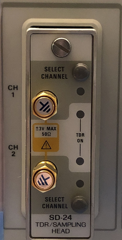
The working SD-24 head mounted on CSA803C
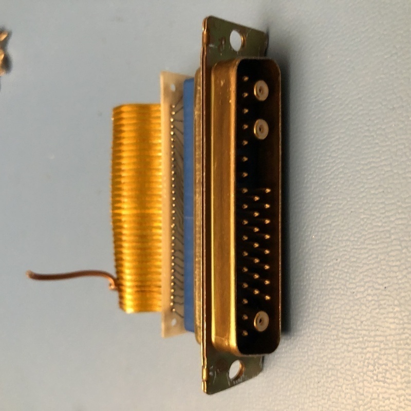
The connector behind SD-24 that is connected to CSA803C
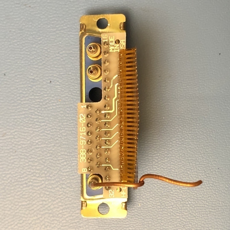
The connector, 3 circular connectors are connected to rigid coax cables, these cables are connected to the board inside, you will see soon. I guess two of them are sampling the signal and one of them might be the strobe input from CSA803C.
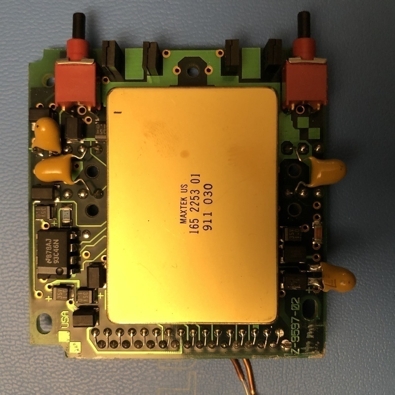
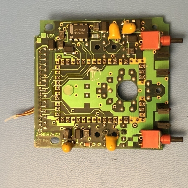
SD-24 board, with a large (I think Tektronix made) IC
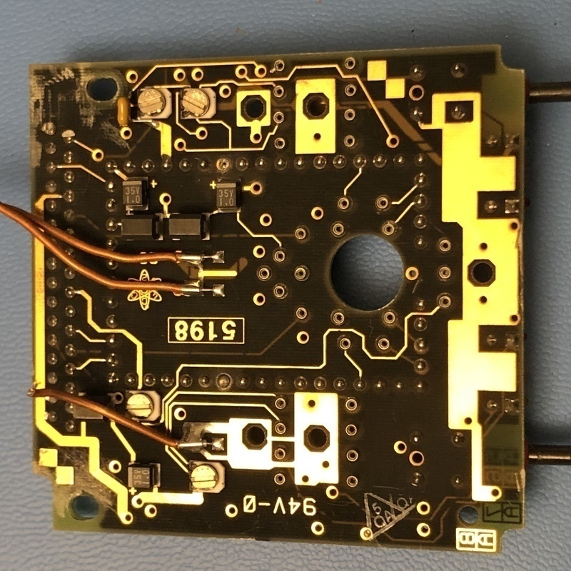
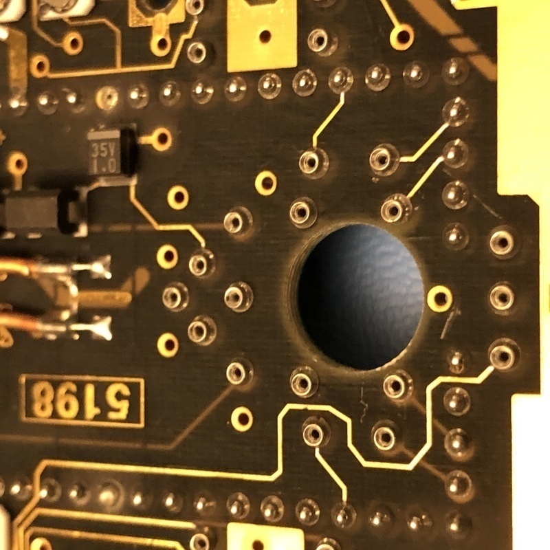
SD-24 board other side, you can see the connections of coax cables coming from the connector
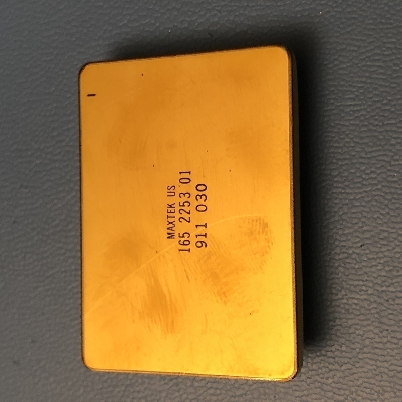
The IC
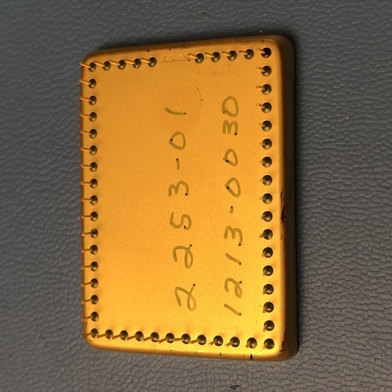
The IC pins side
IC removed, it is mounted on a socket but socket is pretty interesting
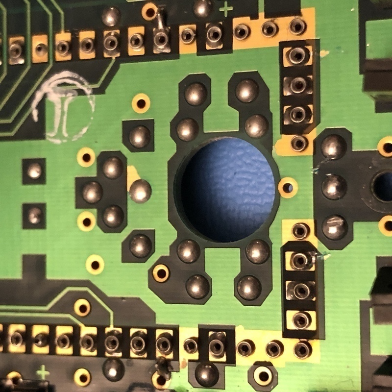
close up IC socket
The board under side, there are also other sockets here which are connected to the block below
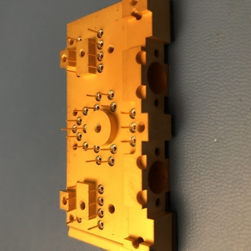
here is the RF block, with pins connecting to the board, and you can see the SMA connectors that is connected to front
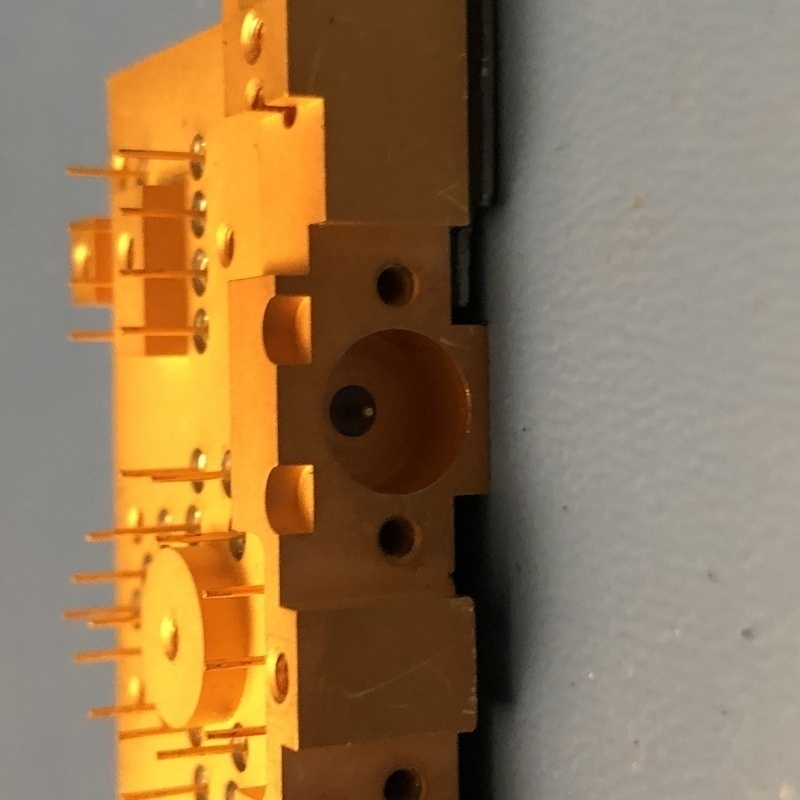
another view of RF block
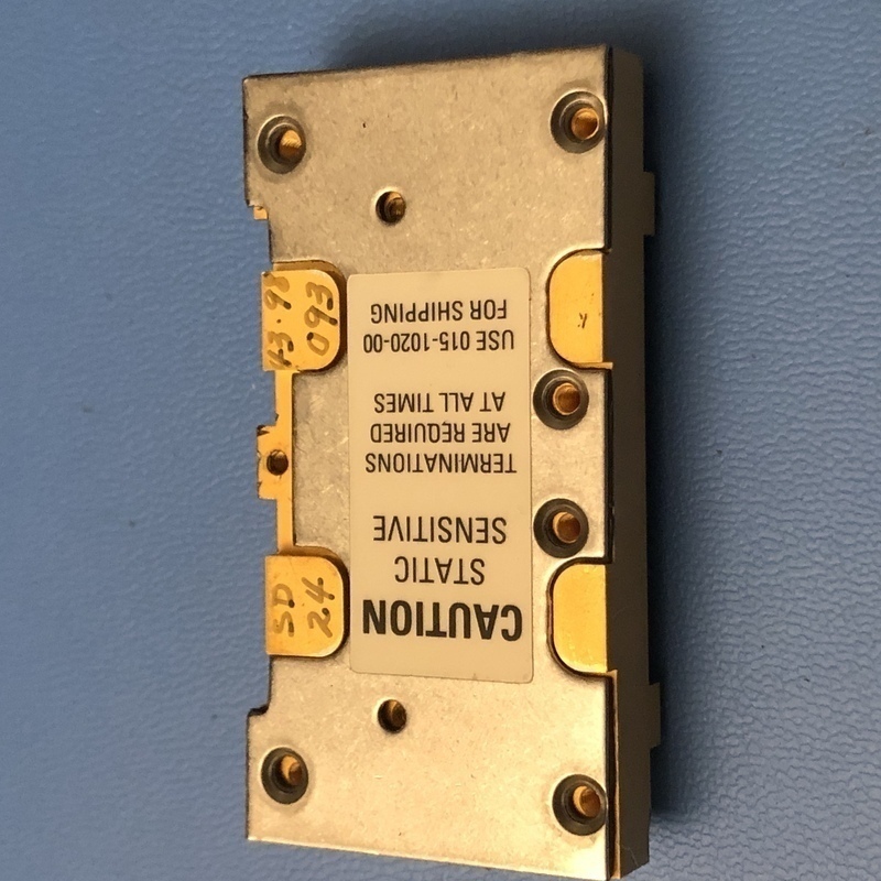
RF block other side, opening this cover reveals the RF circuit
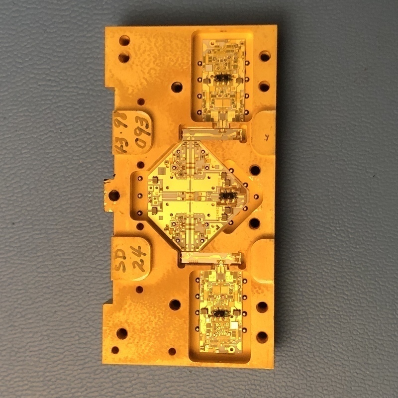
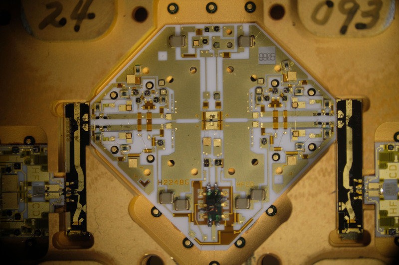
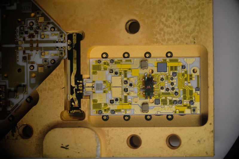
RF circuits
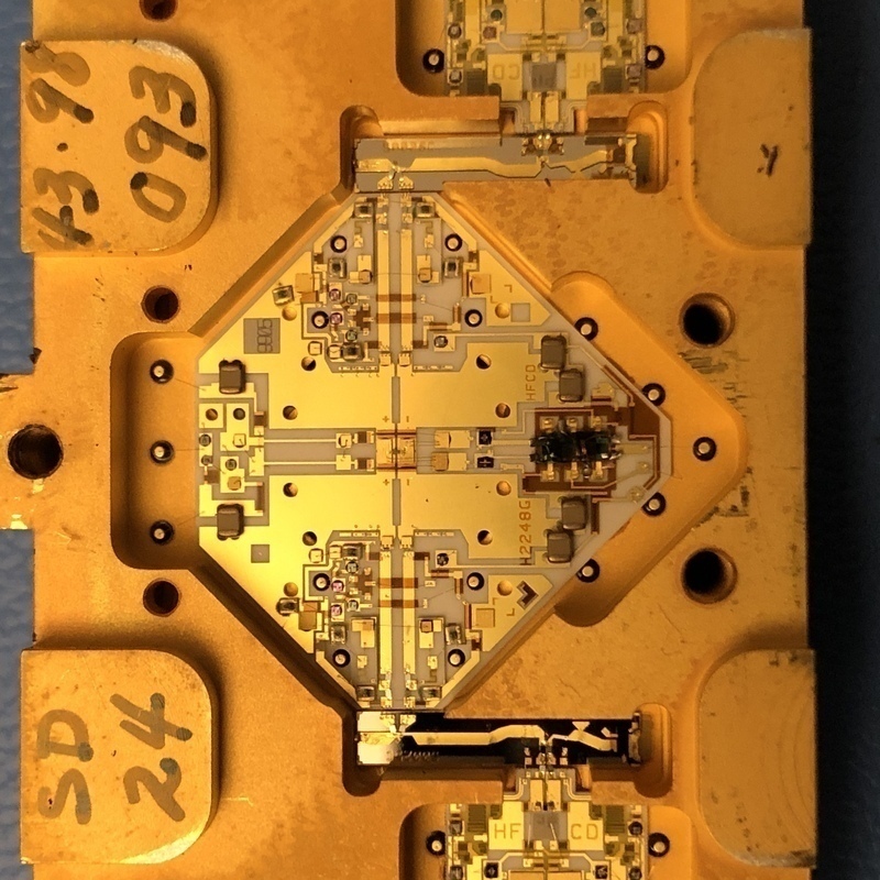
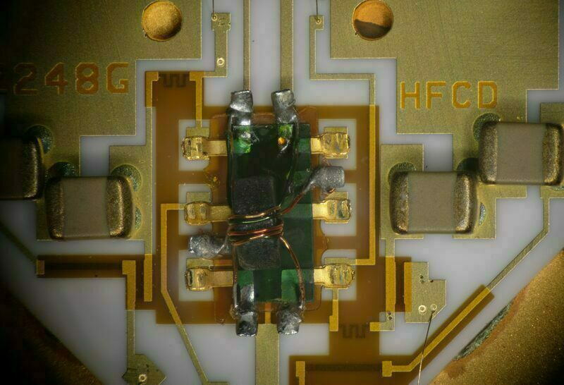
RF circuit, close-up
RF circuit, close-up
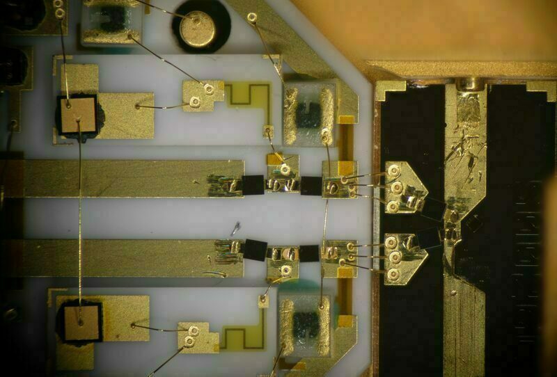
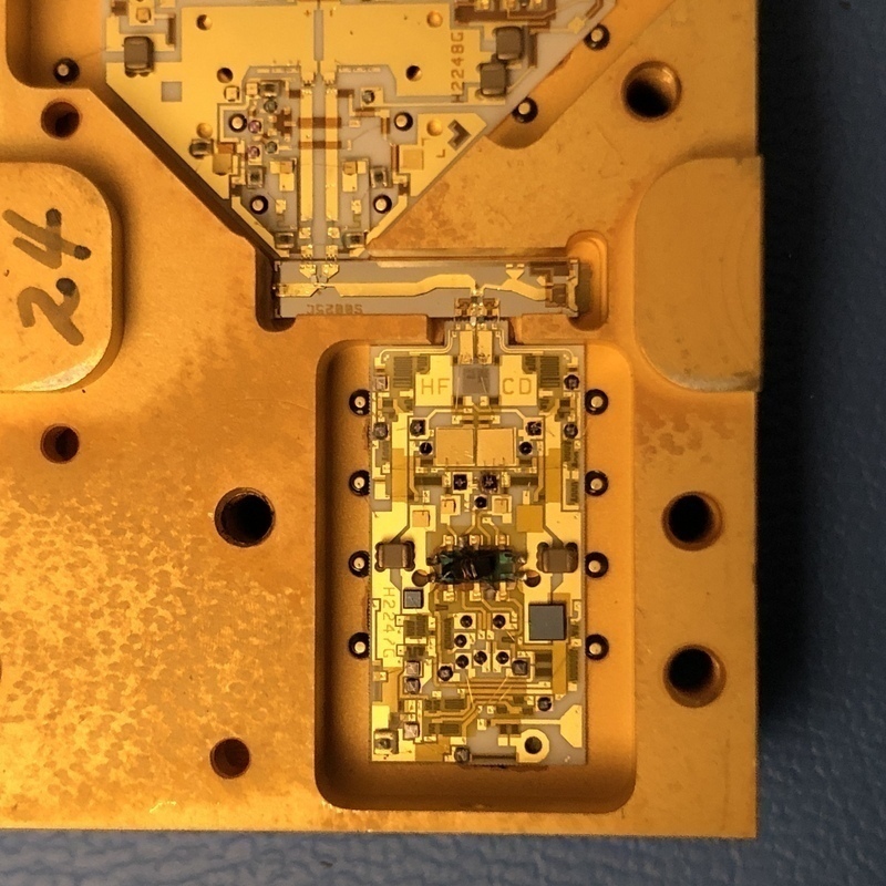
RF circuit under microscope
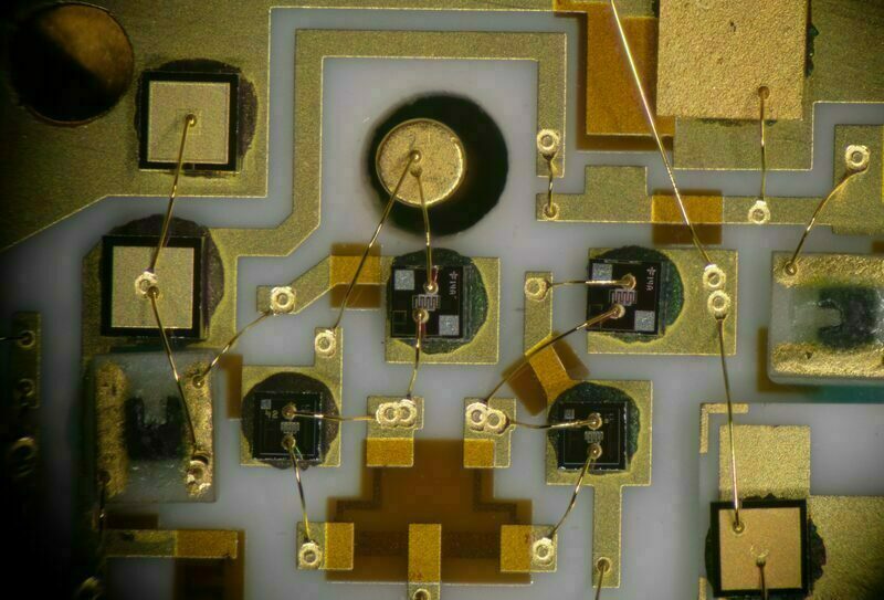
RF circuit under microscope
RF circuit under microscope
RF circuit under microscope
RF circuit under microscope
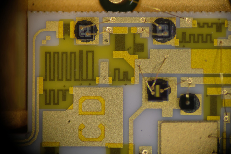
RF circuit under microscope
This work is licensed under a Creative Commons Attribution-NonCommercial-ShareAlike 4.0 International License.