SIMATIC S7-300 CPU 314 Response Time
I wanted to see the the response time of SIMATIC S7-300 that is reading a digital input and writing to a digital output (e.g. the value of the input).
There is a section called Cycle and response times in “CPU 31xC and CPU 31x: Technical specifications” document that explains it in detail.
I have possibly the most simple setup. There is a digital input SM 321 module, and a digital output is taken from SM 322 module, and both modules are on the same rack as CPU 314 (rack 0). OB1 program is just:
   A     "DIN0.0"
   =     "DOUT0.0"
reading one bit and assigning that to output bit. There are no other interrupts happening (no time of day, no time delay, no cyclic). I set the communication overhead to 10%.
Very briefly a typical response should consists of the following:
- the digital input/output delay at the I/O modules
- the input is transferred to memory (process image transfer)
- the output is written from memory (process image transfer)
- the program (OB1) runs
- there are some OS processes after OB1 execution and also during OB1 (for communication etc.)
For CPU 314:
- The process image transfer time is 120us + 8x20us = 280us.
- OS process overhead after OB1 is typically 150us.
- The OB1 overhead is close to 0 (less than 1us probably) because of the very simple program. A bit operation typically takes 0.06us in CPU 314.
So minimum I think should be around 150 + 2x280 = 710us plus input/output module delay. At worst, it can be two times of this value so 1420us plus input/output module delay. The input delay (0 to 1) is specified as 1.2ms to 4.8ms, and the output delay (0 to 1) is given as 100us.
So the minimum should be 710 + 1200 + 100 = 2010us, and the maximum should be 710 + 4800 + 100 = 5610us.
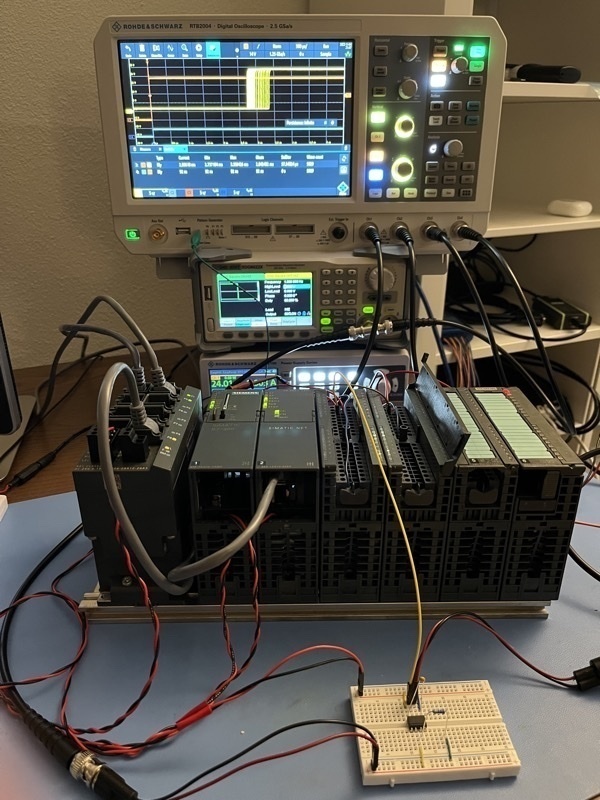
Setup
My setup is:
- Siglent SDG6022X sending 1Hz 5V pulses with 50% duty cycle.
- Because PLC needs 24V, I have an optocoupler (Vishay VOD3120AD), receiving this input and giving 24V output.
- This output is connected to input module. The optocoupler has two (same) outputs, so I use other output to connect to the oscilloscope.
- The output from the output module is connected to the oscilloscope.
- I use a 24V power adapter to power the CPU, SIMATIC NET and SCALANCE switch, and an RS NGE103 power supply for other power needs.
- I use an RS RTB2004 oscilloscope for measurement.
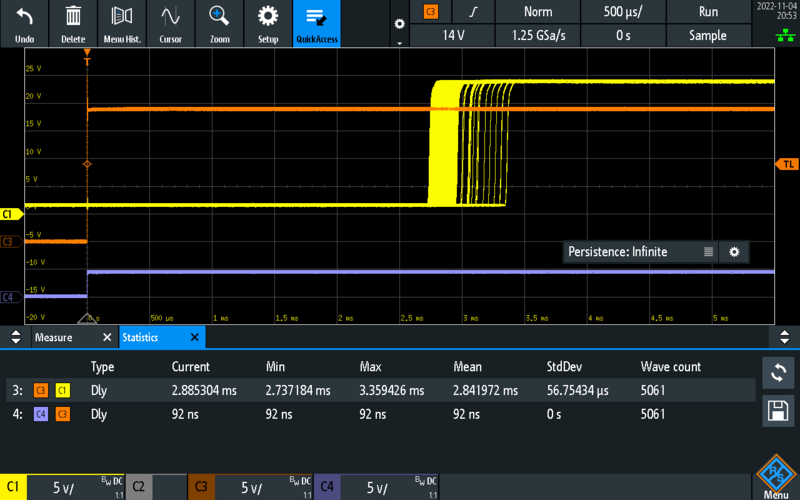
Delay (Measurement 3) with infinite persistence
In the oscilloscope display above:
- C1: PLC output
- C3: optocoupler output / PLC input (C3 is trigger source)
- C4: optocoupler input
The measurement (3) says the average is 2.8ms, and actually most of the measurements are around this value so the spread is small but a few times higher values like 3.3ms can be seen. This is not surprisingly consistent with the above calculation.
One thing to note is optocoupler is very stable at 92ns delay.
This work is licensed under a Creative Commons Attribution-NonCommercial-ShareAlike 4.0 International License.