CADR LISP Machine and CADR Processor
Table of Contents
Introduction
This post contains an overview of the MIT CADR LISP Machine and its processor. The technical information is brief; however, it might be more readable if you have some background in computer architecture. I will repeat things written in the original documents, but I aim to give more or less a complete picture quicker than reading all available documents. I minimized the detailed information about microinstructions because they are mostly similar to a general-purpose processor, but I explained macroinstructions in more detail. These sections can be skipped if you are not interested in this level of detail. I explained the I/O board and diagnostic interface in detail to give a better sense of the system.
It was not initially my intention, but because that is the only way to experience the CADR LISP Machine, I also provide some information and a few hints for the configuration of usim CADR emulator used by the LM-3 project.
What is interesting about the LISP machine besides its historical importance? For example:
Its primary programming language is LISP, so the majority of its operating system is written in LISP.
It runs LISP quite directly. Not in the sense that the processor runs LISP directly at the hardware level, but I am also not sure what this means. If you do not see the microcode, as you do not see it in modern processors, then it is also valid to say the LISP machine runs LISP natively as much as a modern processor runs its machine code natively.
I believe there is no such computer presently, having its operating system almost totally written in a symbolic/high-level language like LISP and executing this language directly at the hardware level.
There are actually four related LISP machines. CONS was built first at MIT, and then CADR was developed as an improvement. Then the commercialization started in 1980: Symbolics released LM-2 and Lisp Machines, Inc. (LMI) released LMI-CADR, both with a license from MIT. All of these four LISP machines are very similar, particularly CADR, LM-2 and LMI-CADR.
Since only about 30 CADR, about 100 LM-2 and about 25 LMI-CADR were produced 40+ years ago, it is not possible to use any of these at the moment. However, it is possible to experience one with the emulator. Because the CADR LISP Machine is not a very complex system compared to a modern computer, studying the emulator source code is not difficult and is also entertaining and informative.
I would like to thank to Alfred M. Szmidt for the clarifications regarding various points in this post.
Clarifications
I use the acronym LISP, not Lisp. I think before about 1975, it was called LISP and then Lisp, as it means LISt Processor. If it is not LisP, LISP makes more sense to me.
I try to use the terms’ microinstruction, microcode, and microprogram consistently. A microinstruction is just a single microinstruction. A microcode contains some microinstructions. A microprogram is a microcode doing a certain job, like a specific function. All of these are also valid when micro is replaced by macro.
In modern processors, only when specifically talking about microcode, the term microinstruction is used. Instruction (without adding micro) means what a developer sees in the instruction set of this processor (such as mov in x86). In this post, I try to be clear by explicitly saying micro or macro every time. However, if I forget to use neither micro nor macro, it should be understood from the context.
Instruction memory, control memory, or control store refer to the same thing. It is the memory where the microcode is stored.
The original (MIT) documents about the LISP machine use octal numbers. I think we are not that familiar with octal numbers anymore (definitely less than hexadecimal numbers). So, I have converted them to hexadecimal numbers in this post, but occasionally I indicate the octal values as well.
Because the memory (main memory and others) is almost always word (32-bit) addressed in the CADR LISP machine, the unit of the memory capacity is Words, not Bytes. For example, 1MW (1 Mega-Words) main memory is physically 4MB (plus parity). It is more complicated for the internal memory areas within the processor because the size of a word changes. For example, 16K instruction memory is physically, I think, 24KB (plus parity) because instructions are 48-bit in CADR. When I write only the magnitude, such as K or M, the unit is Words and the word size depends on the memory type. Thus, 16K instruction memory means 16KW, not 16KB.
In the official documents, there is a term called order code. It means the macrocode (of a compiled LISP expression). I do not know yet where this term “order code” comes from. I am not using it in this post.
Update on 2026-09-26: Clarification by Noel Chiappa: order code is an old jargon from the UK for instruction set, such as The EDSAC Order Code.
There is a term called load band in CADR documents. Load band is a partition (LOD) on the disk, and it contains an image of memory pages at a time, like a snapshot of the current LISP environment. This is used during boot to load the initial system.
LISP
A programming system called LISP (for LISt Processor) has been developed for the IBM 704 computer by the Artificial Intelligence Group at MIT.
John McCarthy in 1959
A milestone in the history of computing is the LISP programming language. LISP was invented by AI pioneer John McCarthy at MIT in the late 1950s and early 1960s. It makes LISP the second major programming language in history after FORTRAN. The first versions of the LISP programming system, LISP I and LISP 1.5, were implemented on an IBM 704 computer.

IBM 704 in 1957 (source: wikipedia)
In History of LISP (1978), McCarthy gives a great historical overview. Here is what I find interesting in this paper:
Initially, the goal was not to develop a new programming language. For example, implementing symbolic computation in FORTRAN was an option. Later, after working on what needed to be done, it became clear that a new programming language was needed.
The initial ideas revealed an “elegant mathematical system as well as a practical programming language”.
IBM 704 was initially chosen because IBM was setting up a computation center at MIT, so it was accessible, and McCarthy was consulting IBM on a different project.
LISP uses prefix notation because the main connective must be determined first before deciding what to do next. If infix were used, a translation program would be needed.
From the start, explicit memory management was not an option (“it was clearly unaesthetic to use explicit erasure as did IPL”). For automatic memory management, there were two alternatives: reference counting and garbage collection. For reference counting, only 6 bits were available for the “count” when it was stored together with the pointer, and it was too small. So, garbage collection was picked. Moreover, it was possible to postpone the actual garbage collection implementation because only simple programs were being done, so there was no need to free the memory. The first implementation was a stop-the-world collector, which runs only when all the memory is exhausted.
Why does LISP represent programs as lists? Actually, it was not initially thought so. However, when writing the
evalfunction, the LISP program was required to be represented as LISP data, which is represented as lists.IBM 704 registers have address and decrement parts and specific instructions to operate on them. LISP I was implemented using these registers, where the first element is pointed by the address field and the remaining is pointed by the decrement field. Thus, the names of functions
carandcdrcome from IBM 704 instructions:carmeanscontents of the address part of register numberandcdrmeanscontents of the decrement part of register number.It was not planned, but after implementing the
evalfunction, it was realized that it could function as an interpreter.After LISP I, it became clear that some improvements and some additional features were needed. This starts the LISP 1.5 work.
There was a LISP 2 project, but it was dropped before it started.
After the first LISP implementations, in the late 60s and 70s, MACLISP at MIT and Interlisp at BBN/Xerox PARC became the most common LISP dialects. Both of these were running on DEC PDP minicomputers. MACLISP was descended from LISP 1.5. “MAC” comes from MIT’s Project MAC.
In fact, the half word instructions and the stack instructions of these machines (DEC PDP-6 and PDP-10) were developed with LISP’s requirements in mind.
History of LISP, McCarthy, 1978
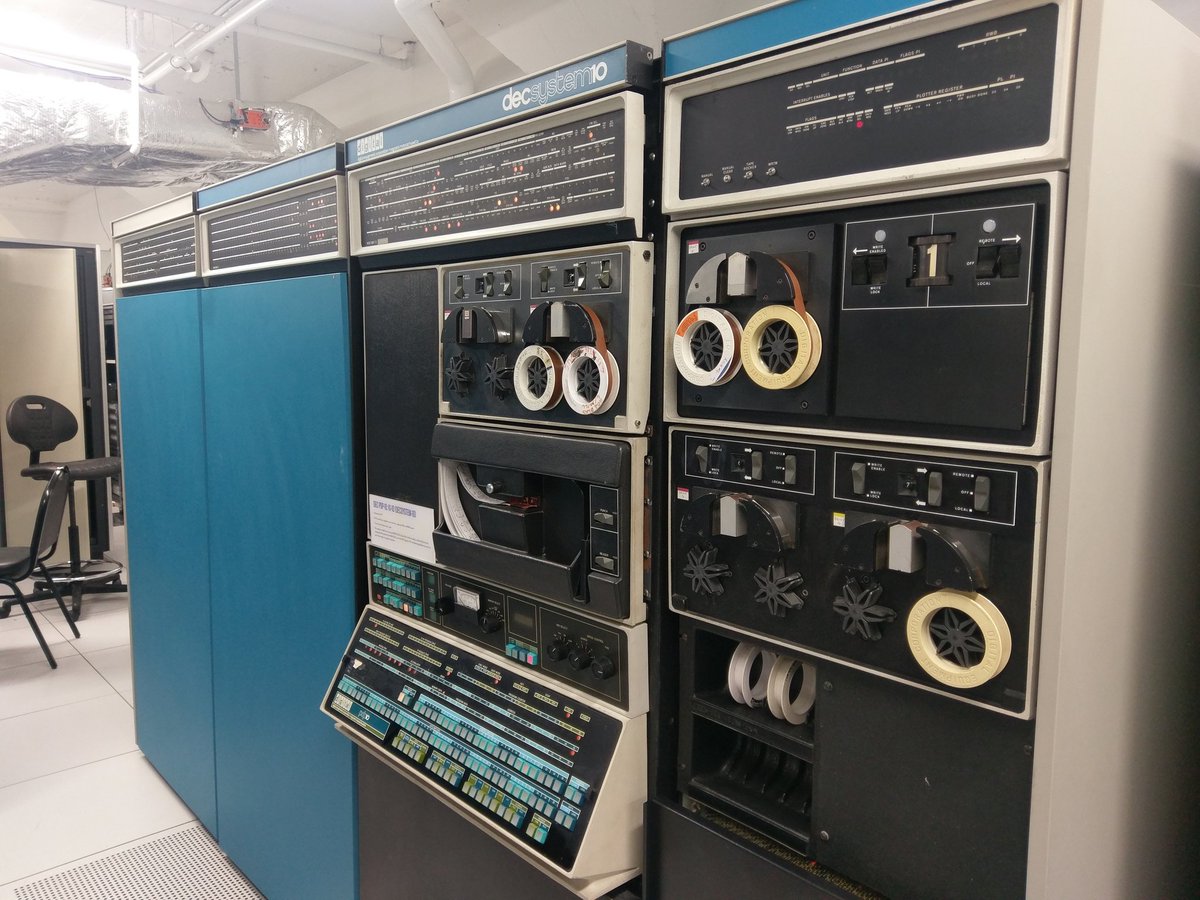
DEC PDP-10 (source: historybit.it)
Why is LISP different from many other programming languages? McCarthy concludes History of LISP (1978) by giving two facts about the longevity of LISP. Among all the reasons he described, I think that having lists representing both data and the program itself gives it a unique position. Interestingly, McCarthy and others have regarded this as a disadvantage.
CADR LISP Machine
The main problem of using LISP on these mainstream general-purpose computers is the limited amount of memory and low performance. Both PDP-6 and PDP-10 have 36-bit data word and 18-bit addressing (max. 256K words).
The idea of a “LISP machine” has been kicked around more or less constantly
since t=-∞.Richard Greenblatt, 1975
It appears that the idea of a LISP machine has been in people’s minds since LISP was invented. Probably, it only became technologically possible around 1975. The idea of a LISP machine with more memory and faster execution speed was attractive.
Richard Greenblatt, Jack Holloway and Tom Knight started working on the CONS LISP Machine in the summer of 1974, this is also called the Knight Machine. A revision of this machine, called CADR, was built in the following years in late 1970s. We know that there were four operational machines in December 1978. This machine was well received, and about 30 CADR Machines were built at MIT. The story of Symbolics and Lisp Machines, Inc. (LMI) starts at this point.

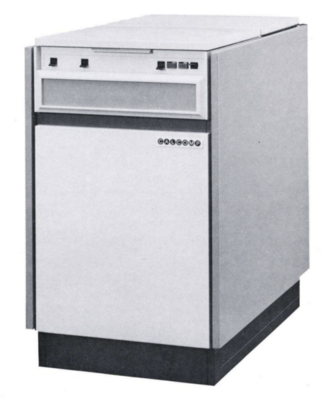
CADR LISP Machine (source: wikipedia)
CADR was designed to be a LISP machine; however CADR processor was a microprogrammed general purpose processor. CADR processor, together with its microcode, was “interpreting” LISP. Thus, LISP Machine means the processor and the microcode together.
CONS and CADR are very similar, but because CADR is an improved design, and is much more famous, I focus on CADR in this post.
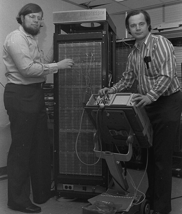
R. Greenblatt (right) and T. Knight (left) with CADR LISP Machine at MIT (source: Computer History Museum)
System Overview
CADR LISP machine has 32-bit data word, and 24-bit virtual, and 22-bit physical addressing. It also has Unibus and Xbus. Unibus is the standard 16-bit PDP-11 bus.
It is a bit difficult to find information about the CADR LISP machine as a system, so I also use the LM-2 documents. I believe it comes in a cabinet of ~21U rack height. This cabinet includes two cages: a cage for 6 processor boards, and a cage for Unibus and Xbus cards or boards. The disk drives are separate (and big and heavy) units. By default, I think, it comes with 3 boards:
- I/O board (also called IOB) (Unibus): for keyboard and mouse and a few other things
- disk interface board (Xbus): to connect a disk drive
- bitmap interface board (Xbus): to connect a display
There are plenty of available slots for expansion. On LM-2, there are 10 Unibus slots, and I think there are 22 Xbus slots. Some cards may consume the space of 2 slots due to their construction. Lots of expansion slots are needed because, for example, the main memory is also installed on Xbus.
It is possible to connect a disk drive unit to the disk interface board. With a multiplexer board, 7 additional disk drive units can be connected.
Here is a system diagram from the official documents; I made a redraw for clarity. Disk interface board is shown as Disk control, and bitmap interface board is shown as TV control.
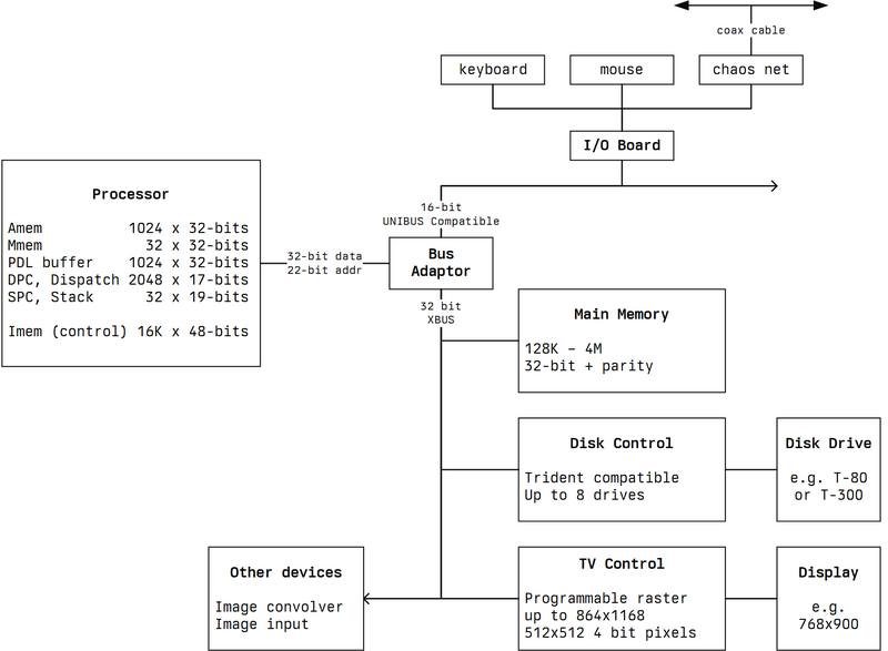
CADR LISP Machine System Diagram (redrawn based on AI Memo 528)
It is probably not obvious that the processor is not a single (VLSI) IC chip. It is built from many other basic ICs, since VLSI technology was just starting in the 1970s. The same is true for the functionality implemented by the boards.
For example, the 32-bit ALU of the processor is implemented using the 74181 4-bit ALU IC, and there are 9 of these and some other ICs just for implementing the ALU block.
For example, the bitmap memory of the TV control is implemented with 4116 16 Kbit memory ICs; thus, there are 64 of these memory ICs to implement 1024 Kbit memory to support, for example, an 800×1024 monochrome display.
CADR schematics are available.
All the memory blocks of CADR LISP machine have parity checking. A parity error in internal memories can cause the machine to be halted. A parity error in main memory can halt the machine, cause a microcode trap, or can be ignored, depending on mode flags.
LISP as a System Language
These are some useful points from LISP Machine Progress Report, 1977, LISP as a System Language section:
The software in LISP machine is coded only with LISP and CADR machine microcode.
For some low-level operations, some “sub-primitive” functions exists, and their names start with a
%.Memory paging is handled by microcode and is not visible to LISP code.
The input/output software is totally written in LISP, using only
%UNIBUS-READand%UNIBUS-WRITEsub-primitive functions.There are also some microcoded display-related functions to speed up the drawing of characters. These are microcoded for performance reasons.
Unibus
I/O Board (IOB)
Having an IOB seems like a must, as it supports the following basic devices (ordered by Unibus locations/addresses):
- Keyboard: The data from the keyboard is encoded as a 32-bit word read from Unibus locations 0x3E840 (low 16-bit) and 0x3E842 (high 16-bit) (764100 and 764102 octal). It generates an interrupt, vector number 260. The LM-2 keyboard has 100 keys. This keyboard was originally called Space Cadet keyboard. You can also watch a youtube review.

Symbolics LM-2 Keyboard (source: wikipedia)
- Mouse: Also called “Display Cursor Positioner”. Because there are no arrow keys, I think it was often used for this purpose. The X-position (as a relative position) is at Unibus location 0x3E846 (764106) and the Y-position and the buttons are at 0x3E844 (764104). It is polled 60 times per second. It can also generate an interrupt (vector number 260, same as the keyboard), but I think the interrupt is not used.
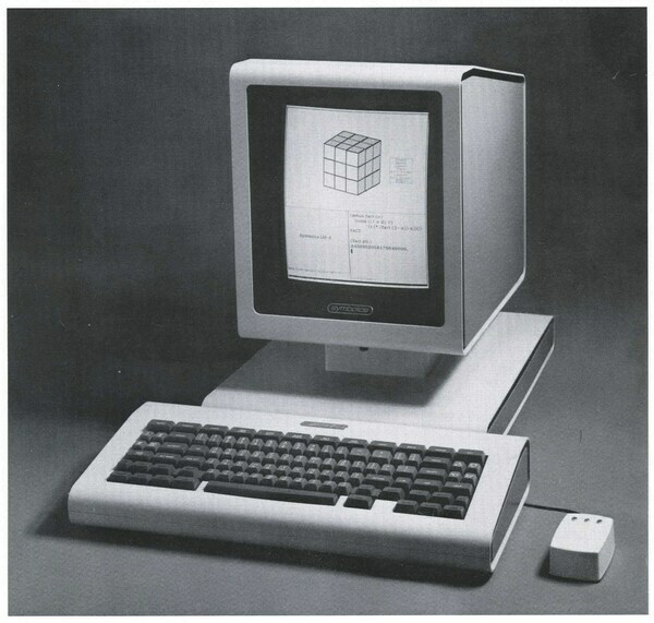
Symbolics LM-2 Keyboard, Mouse and Display (source: Symbolics LM-2 Brochure)
Speaker: There is a simple speaker inside the keyboard. The
beepfunction can be used for this. Reading the Unibus location at 0x3E848 (764110) inverts the state of the bit that generates the sound.Microsecond Clock: It is a 32-bit register that increments every microsecond. Its value can be accessed using the functions
time:microsecond-timeandtime:fixnum-microsecond-time. These functions read from the Unibus locations at 0x3E850 (low 16 bits) and at 0x3E852 (high 16 bits) (764120 and 764122 octal).60-Hz Clock: It is a 16-bit register that increments every 1/60 second. This clock is driven by the AC power line, so the accuracy is poor in the short term, but good in the long term. Its value can be read at Unibus location 0x3E854 (764124 octal). Because the register is not synchronized to the bus clock, it has to be read multiple times, and its value is valid only when two consecutive values are the same.
Interval Timer: It is a 16-bit register that decrements every 16 microseconds and generates a Unibus interrupt when it reaches zero. It can be programmed by writing to Unibus location 0x3E854 (764124 octal). Its value cannot be read, but it generates an interrupt when it reaches 0. The interrupt vector number is 274.
General Purpose I/O Port: This is a 16-bit parallel bidirectional port. It is not used by the system, but it can be used by the user using
%unibus-readand%unibus-write. The 16-bit register for this port is at Unibus location 0x3E856 (764126 octal).Chaosnet: This is a pre-Ethernet local computer network. The chaosnet interface is at Unibus location 0x3E860-0x3E86A (764140-764152 octal), and the interrupt vector number is 270. The IOB contains two DIP switches to set the Chaosnet network address, controlling the subnet number and the host number. The address is formed by concatenating the subnet number (8-bit) with the host number (8-bit). The address can be read from the Unibus location at 0x3E862 (764142 octal).
Serial I/O Port: It is a general-purpose synchronous or asynchronous (RS-232) serial data port. It is located at Unibus location 0x3E870-0x3E876 (764160-764166 octal). The serial port uses interrupt vector number 264.
Diagnostic Interface
The Diagnostic Interface is accessible on Unibus. It has 16 locations for reading, and 8 locations for writing. The same address for read and write does not mean they refer to the same thing.
My understanding is that this interface has at least two purposes. One is taking part in the boot process, particularly using the mode register. The second is to facilitate debugging, probably by connecting another computer, a PDP-11, to this interface.
Below, I just summarize what is in the original documents to give a sense of this interface.
Read Locations
These readable locations are also called “Spy Feature”, as it allows one to spy internal machine operations.
| Location | Description |
|---|---|
| 0x3EC00 | IR[15:0], IR is Instruction Register |
| 0x3EC02 | IR[31:16] |
| 0x3EC04 | IR[47:32] |
| 0x3EC06 | not used |
| 0x3EC08 | the last OPC Register (containing the value of PC 8 clocks ago) |
| 0x3EC0A | PC, PC is Program Counter |
| 0x3EC0C | OB[15:0], OB is Output Bus |
| 0x3EC0E | OB[31:16] |
| 0x3EC10 | Flag Register 1 |
| 0x3EC12 | Flag Register 2 |
| 0x3EC14 | M-source[15:0], selected by IR |
| 0x3EC16 | M-source[31:16], selected by IR |
| 0x3EC18 | A-source[15:0], selected by IR |
| 0x3EC1A | A-source[31:16], selected by IR |
| 0x3EC18 | ST[15:0], ST is Statistics Counter |
| 0x3EC1A | ST[31:16] |
Flag Register 1
| Bit | Name | Description |
|---|---|---|
| 15 | ~WAIT | 1 if the machine is running, 0 if it is waiting for the memory |
| 14 | ~V1PE | 0 if level-2 map had a parity error at the last clock |
| 13 | ~V0PE | 0 if level-1 map had a parity error at the last clock |
| 12 | HIGHOK | 1 if power-supply check is OK |
| 11 | ~STATHALT | 0 if the machine has been stopped by the statistics counter |
| 10 | ERR | 1 if an error condition is present |
| 9 | SSDONE | 1 if a single-step has been completed. |
| 8 | SRUN | 1 if the machine is trying to run (but it may be stopped) |
| 7 | ~HIGHERR | 1 if there was HIGHOK at the last clock |
| 6 | ~MEMPE | 0 if there was a main memory parity error |
| 5 | ~IPE | 0 if there was a control memory parity error |
| 4 | ~DPE | 0 if there was a dispatch memory parity error |
| 3 | ~SPE | 0 if there was an SPC stack parity error |
| 2 | ~PDLPE | 0 if there was a PDL-buffer parity error |
| 1 | ~MPE | 0 if there was a M-memory parity error |
| 0 | ~APE | 0 if there was a A-memory parity error |
Flag Register 2
| Bit | Name | Description |
|---|---|---|
| 15 | unused | |
| 14 | unused | |
| 13 | VMAPD | previous cycle indicated a write to the map |
| 12 | DESTSPCD | previous cycle indicated a write to SPC stack |
| 11 | IWRITED | |
| 10 | IMODD | |
| 9 | PDLWRITED | previous cycle caused a write into PDL-buffer |
| 8 | SPUSHD | previous cycle caused a write into SPC stack |
| 7 | unused | |
| 6 | unused | |
| 5 | IR[48] | parity bit of IR |
| 4 | NOP | 1 if the current instruction is a NOP |
| 3 | ~VMAOK | The last main memory cycle was failed because the map indicated a page fault |
| 2 | JCOND | 1 if the jump-condition is satisfied |
| 1:0 | PCS1-0 | Next PC selector 0: SPC Stack 1: IR[25:12], address specified by a JUMP2: DPC[13:0], the dispatch memory 3: IPC[13:0], PC+1 |
Write Locations
Here are 8 writable locations:
| Location | Description |
|---|---|
| 0x3EC00 | DEBUG-IR[15:0] |
| 0x3EC02 | DEBUG-IR[31:16] |
| 0x3EC04 | DEBUG-IR[47:32] |
| 0x3EC06 | Clock control register |
| 0x3EC08 | OPC control register |
| 0x3EC0A | Mode register |
| 0x3EC0C | not used |
| 0x3EC0E | not used |
Clock Control Register
| Bit | Name | Description |
|---|---|---|
| 4 | LDSTAT | setting this to 1, then clocking the machine, causes the statistics counter to load from IWR[31:0]. |
| 3 | IDEBUG | setting this to 1 causes IR to load DEBUG-IR instead of the PROM or the instruction memory |
| 2 | NOP11 | setting this to 1 forces NOP in this cycle. |
| 1 | STEP | setting this to 1 when SSDONE is 0 causes the processor clock to run for one cycle and then set SSDONE. |
| 0 | RUN | setting this to 1 causes the machine to start running |
OPC
There are 8 OPC registers that keeps the last 8 PC values. Only the last OPC register that keeps the PC value 8 clocks ago can be read.
OPC control register contains bits that is used to restore the state of the machine from a saved state. Its fields are:
| Bit | Name | Description |
|---|---|---|
| 2 | OPCINH | setting this to 1 inhibits the OPCs from being clocked by the processor clock. it is used for loading OPCs by executing JUMPs |
| 1 | OPCCLK | setting this to 1 and then 0 (thus making a high-low transition) generates a clock to shift OPCs, it is used for reading OPCs |
| 0 | LPC.HOLD | setting this to 1 prevents LPC register from loading the PC register when the machine is clocked. it is used by IR<25> in DISPATCH instruction. |
Mode Register
| Bit | Name | Description |
|---|---|---|
| 7 | PROG.BOOT | setting this to 1 starts a bootstrap sequence |
| 6 | PROG.RESET | setting this to 1 resets the machine |
| 5 | PROMDISABLE | 1 disables the PROM. 0 replaces the the first 1K locations of control memory with the PROM. |
| 4 | TRAPENB | setting this to 1 causes main memory parity errors to cause microcode traps at location 0. |
| 3 | STATHENB | setting this to 1 enables overflow of the statistics counter to halt the machine |
| 2 | ERRSTOP | setting this to 1 enables hardware errors (HIGHERR and various parity errors) to halt the machine. |
| 1:0 | SPEED | 0: Extra Slow, 1: Slow, 2: Normal, 3: Fast |
In addition to SPEED bits, ILONG bit in the instruction affects the speed (by slowing it down by 40 nanoseconds).
Xbus
The main memory, the disk, and the display are connected to Xbus. Xbus is 32-bit wide.
It is possible to install up to 4M words (22-bit) of main memory. It is possible to use 16M words (24-bit) of virtual memory with paging on the disk.
The disk drives can be T-80 80 MB (shown on the diagram) or T-300 300 MB disks (maybe also others, but these are the ones I always saw in various documents). T-300 is a 3600 rpm disk drive using IBM 3336-11 disk packs. As a reminder that we are talking about the 1970s, T-300 weighs 218kg.
Trident T-300 Disk Drive (source: CalComp T-300 Brochure, 1976)
It is also possible to attach a magnetic tape drive and controller (I guess the controller is a Xbus board).
A bitmap interface board is needed to attach a display. Then either a high resolution 768×900 monochrome or a 512×512×8bpp color monitor can be used. LMI documents also mention an 800×1024 display.
On CADR documents, it is mentioned that the raster memory for display is up to 864×1168 monochrome or 512×512 4-bit pixels.
PROM and Bootstrapping
When CADR LISP machine is powered on, it resets itself, but it does not automatically start. The start/boot can be initiated in various ways (even from the chaos network interface). The most common is to use the keyboard, as the machine recognizes a special set of keyboard commands to start booting, typically left and right control-meta keys.
When boot is initiated, the machine resets and halts. Then it turns on “RUN”, but nothing works because the clock is not running. After starting the clock at the slowest speed, it disables checks and halts, and then enables PROM. PROM is a read-only control memory. The control jumps to location 0 of PROM. The code in PROM:
- clears all internal memories (and fills the correct parity bits)
- resets the Unibus
- enables checks and halts
- sets the machine speed to normal
- runs diagnostic checks
- loads the microcode from the disk (from an MCR partition)
- loads the initial contents of main memory from the disk (from an LOD partition)
- transfers control to the microcode at its start address, which is taken from the diagnostic interface
I explain the disk partitions in the next section.
The switch from PROM to instruction memory is done with the PROGDISABLE bit of the Mode register, which is modified with a write on Unibus.
On a real LISP machine, PROM is a real IC, but on the emulator, a PROM dump has to be given. On LM-3 System 100, it is stored as sys/ubin/promh.mcr. Naturally, this should contain microcode (hence the mcr extension). The development of the usim emulator started with the PROM images. Brad Parker wrote: “… Certainly if Al (Kossow) had not sent me the PROM images I would never have started. …” (source: unya/usim repository).
Disk Partitions
PROM starts and boots the LISP Machine by loading microcode and the initial contents of memory from the disk.
The disk controller is said to be Trident compatible, so it supports Trident disk drives. usim emulates a Trident T-300 disk drive.
The disk contains a label in the first block (1 block=256 words=1024 bytes). The label contains information about the disk (number of cylinders, heads, blocks per track etc.) and the partition table. Each partition has a name, start block, size in blocks, partition type and a comment or description. The number of partitions is not fixed (but I only saw one example, so I am not sure if there is any limitation somewhere else). The layout of the disk that comes with LM-3 has 18 partitions named: MCR1 to MCR8 (Microcode), PAGE, LOD1 to LOD8 (Load) and FILE. An MCR partition contains a microcode dump. An LOD partition contains an initial system, a memory dump. So, the boot process is as simple as:
- restoring the microcode dump from an MCR partition on the disk to the Instruction Memory
- restoring the memory dump from an LOD partition on the disk to the PAGE partition on the disk (why PAGE, continue reading)
One of the MCR and one of the LOD partitions are used during boot. These are called the current MCR and current LOD partitions and this information is written on the disk label as well.
Other than the MCR and LOD partitions, there is a PAGE partition. This is the virtual memory paging area. This is why the current LOD is copied to the PAGE during boot. An LOD partition is also called a “load band”.
The process above describes cold-booting. In warm-booting, the memory dump stored in the LOD partition is not loaded to PAGE, thus the existing PAGE partition (existing memory content) is retained and used.
After MCR and LOD partitions are copied, the machine starts from (thus LC is set to) whatever %INITIAL-FEF is mapped to. This is normally the function LISP-TOP-LEVEL in SYS:SYS;LTOP.LISP. (Thanks to Alfred M. Szmidt for the clarification)
usim emulator has a diskmaker tool for creating and manipulating T-300 disk images. On LM-3 System 100, it shows:
$ ./usim/diskmaker -p -f disk-sys-100-0.img
##
output:
disk-sys-100-0.img
##
label:
cyls	815
heads	19
blockspertrack	17
brand	Trident T-300
text	MIT-LISPM-1
comment	System 100 Distribution Tape
mcr	MCR1
lod	LOD2
##
partitions:
MCR1	021	0224		UCADR 323
MCR2	0245	0224
MCR3	0471	0224
MCR4	0715	0224
MCR5	01141	0224
MCR6	01365	0224
MCR7	01611	0224
MCR8	02035	0224
PAGE	02414	0200000
LOD1	0202414	057241		cold 3/23/23
LOD2	0261655	057241		Exp 100.0
LOD3	0341116	057241
LOD4	0420357	057241
LOD5	0477620	057241
LOD6	0557061	057241
LOD7	0636322	057241
LOD8	0715563	057241
FILE	0775024	05071
You can see at the top comment System 100 Distribution Tape, which I think indicates this is restored from a tape. Also, mcr MCR1 and lod LOD2 shows the names of current MCR and LOD partitios that are used at boot. I guess when you get one of these LISP machines, it comes with one or more tapes, and they are restored to a disk first.
Above, it shows that all MCR partitions are 224 blocks and all LOD blocks are 57241 blocks. PAGE is 200000 (200K) blocks. “Each disk block contains one Lisp Machine page worth of data, i.e. 256 words or 1024 bytes” says the comment in usim/disk.c. The virtual memory addresses are 24-bits, so 16M words. The PAGE partition has 200000 blocks, which is 51.2M (200000 * 256) words, more than the maximum addressable virtual memory size.
Instead of using Chaosnet, the FILE partition can also contain a local file system. (Thanks to Alfred M. Szmidt for the clarification)
Indicators
On a real LISP machine, there are 5 octal displays showing the current value of PC, and the decimal points of the display show:
- PROMENABLE, indicating if the current instruction is from PROM
- IPE, DPE, TILT0, and TILT1, indicating parity errors in various memories
Price
Since Symbolics Price List from 1980 is available, let’s check how expensive it was:
- The base Lisp Machine Model 2 (LM-2) with 12K microcode memory was ~80K USD.
- An 64K word memory module costs ~5K USD.
- Adding I/O-bus module costs 6K USD. The keyboard, mouse, and chaos net interface cost ~7K USD. Total ~13K$USD.
- Adding a T-300 disk (300 MB) costs 5K USD for the interface and 30K USD for the disk drive, for a total of 35K USD.
- Adding a monochrome display costs ~7K USD for the bitmap interface and ~5K USD for the monitor, for a total of 12K USD.
- LM-2 operating system costs 20K USD.
So, an LM-2 with 1M memory, and 300MB disk costs ~240K USD.
CADR Processor
CADR processor is a general-purpose processor, but its architecture is optimized for interpreting LISP macrocode.
I would say the processor is a von Neumann architecture, as the data and (macro) instructions are fetched over the same bus; however, there are two types of instructions, and they stay in different memories. The microinstructions are what the processor actually executes (in hardware), and they are stored in a separate (16K) instruction memory. The macroinstructions stay in the main memory (up to 4M physical, 16M virtual).
CADR processor:
- fetches a macroinstruction from the main memory over XBus
- finds the location of its “micro” implementation within the instruction memory
- calls this location to execute this microprogram
- when the microprogram is done, after it returns, it fetches another macroinstruction
It is like the CADR processor has a von Neumann architecture for macroinstructions, but a Harvard architecture for microinstructions.
It can be said that the CADR processor is emulating the macroinstruction with the microinstructions. Today, we can say it could be done (and it is done with the emulator) that the emulation could be done purely in software. However, it is much faster with hardware assistance (particularly in the 1970s and in the 1980s).
I am not sure if it is a fair comparison, but below you can find CADR Processor vs. Motorola 68000. Motorola 68000 was introduced in 1979, and it was quite an advanced general-purpose processor (for example, it was used in Amiga 1000 in 1985). Below is a comparison of basic features, not taking into account that the architecture of CADR is optimized for executing LISP:
| Feature | CADR | Motorola 68000 |
|---|---|---|
| Instruction Set | 16-bit macro 48-bit micro | 32-bit 17-bit micro |
| Data Bus | XBus 32-bit Unibus 16-bit | 16-bit |
| Registers | 1024 32-bit register memory | 8 32-bit data registers 8 24-bit address registers |
| Address Bus | 24-bit virtual 22-bit physical | 24-bit |
| ALU | 32-bit plus Hardware Shifter and Masker | 16-bit |
| Instruction Cycle | typically 180ns (variable clock) | 250 ns (4MHz) |
A full 32-bit version of 68000, 68020, was launched in 1984.
68000 is a complex instruction set computer (CISC) microprocessor, and it also has a microcode, but the microcode is not visible to the user. Using the microcode, 68000 provides its instruction set.
In early microprocessors (1980s), the microcode stays in a read-only memory (ROM) or programmable logic array (PLA). In a CADR processor, microcode has its own memory and is fully programmable.
Looking at it this way, it can be said, the instruction set of the CADR processor is macroinstructions. That is why I wrote before that it is not strange to say the CADR processor is executing LISP directly.
Features
CADR Processor has the following (uncommon) features:
| Feature | CADR |
|---|---|
| A scratchpad/memory | 1024 (1K) locations 32-bit wide |
| M scratchpad/memory | 32 locations 32-bit wide |
| PDL/Stack buffer | 1024 (1K) locations 32-bit wide |
| SPC memory, subroutine return stack | 32 locations 19-bit wide |
| PC (Program Counter) | 14-bit wide |
| Instruction Memory | 16K locations 48-bit wide |
| DPC, dispatch memory | 2048 (2K) locations 17-bit wide |
| IR (Instruction Register) | 48-bit wide microcode |
| Q register | 32-bit |
| LC (Location Counter) | 26-bit wide |
| ST (Statistics Counter) | 32-bit wide |
The processor has a 32-bit data path, a 24-bit (virtual) address path, and a 32-bit ALU including a Masker and a Shifter.
PC (Program Counter) points to the next microinstruction in instruction memory. Instruction memory is 16K, and hence PC is 14-bit wide.
LC (Location Counter) points to the next macroinstruction in the main memory. It is byte addressed and supports byte or half-word addressing. In the case of half-word addressing, the last bit is 0. Since the virtual address width of the system is 24-bit, the size of LC is 26-bits.
You might ask, where are the registers? There are no registers similar to our current processors. However, A and M scratchpads are used like registers. In that case, there are a lot of (1024) registers in the CADR processor. M scratchpad is actually a copy of the first 32 locations of A scratchpad. It is like having a dual port memory for the first 32 locations, thus making it possible to use these in more flexible ways.
SPC keeps the PC values and is used as a subroutine return stack. Not similar to modern processors, where the stack is in the main memory, SPC is implemented separately, so its size is fixed. This means only 32 subroutine calls can be nested. The subroutine here is a subroutine of microcode, not a LISP (macro) function. In addition to PC values (14-bit), there are 5 “software” bits. The 14th bit (one of the software bits) is used to mark the end of a macroinstruction execution.
Dispatch memory is quite interesting. It contains 17-bit entries, where each entry is formed as R bit, P bit and N bit, and a 14 bit address for PC.
- R bit is to ignore PC but pop one from the stack (SPC) (for RETURN operation)
- P bit is to push PC to the stack (SPC) (for CALL operation).
- N bit is to inhibit the execution of next microinstruction (more about this later)
If P and R are both zero, then it is like a BRANCH or unconditional JUMP instruction. So, a single entry can encode a RETURN, CALL or unconditional JUMP/BRANCH operation.
If P and R are both one, then DISPATCH is not performed. However, with miscellaneous functions, it is possible to write to the dispatch memory.
PDL buffer is a memory with a hardware “push-down” pointer that improves the performance of stack operations as they are very common in LISP execution. It is basically a hardware stack.
A microinstruction is 48-bit wide; hence IR is 48-bits.
Q register is primarily used to help with multiplication and division.
Statistics Counter (ST) is incremented if the statistics bit (46th bit) of a microinstruction is 1. If ST overflows from -1 (0xFFFFFFFF) to 0, and if STATHENB of the mode register is 1, then the machine stops. Bit 46 is 0 for all PROM microinstructions. Statistics Counting can be used for metering, debugging and breakpointing.
Other than these internal memories, there is no instruction or data cache as in modern processors.
Pipeline
It is not described like this in the original documents, but I think the CADR processor can be considered a 2-stage fully pipelined processor. A microinstruction is fetched at every cycle, and the fetch of the next microinstruction overlaps the execution of the current instruction. Because of this, when a branch is taken, the next instruction becomes invalid, and its execution is inhibited.
C: cycle
F: fetch
E: execute or store

---- time --->
C1 C2 C3 C4 C5
F2 F3 F4 F8 F9
E1 E2 E3 -- E8

At C3, due to E3, a branch is taken (to PC=8), thus E4 is inhibited.
Naturally, the inhibited execution cycle is wasted. The inhibition is signaled by using the N bit in the change of control instructions, where:
- N bit is stored with the instruction for a conditional JUMP instruction
- N bit is stored in the dispatch memory entry for a DISPATCH instruction
Clock and Cycle Timing
CADR processor has one clock signal. As far as I understand, the clock is generated and controlled separately for the processor and the bus.
The control signals of the A and M scratchpads, PDL buffer, and SPC stack are asynchronous, but it is not visible to the user. The reason for the pass-arounds in data paths (shown in the next section) is this, and these are also not visible to the user.
I think it can be said that the clock is active high, but both halves (or transitions) are used. The first half is the read phase and the second half is the write phase. Unlike any modern processor, the clock cycle is not fixed. The duration of the first half (when the signal is high) is controlled by ILONG bit of the instruction, so an instruction may indicate it requires more or less time, and by two “speed” bits from the diagnostic interface. The duration of the second half (when the signal is low) is normally fixed.
The clock can be stopped at the end of the read phase, and this is called a wait. A wait happens because:
- halt is requested from the diagnostic interface
- single-step is requested from the diagnostic interface
- an error (such as parity) happened
- statistics counter is overflowing
- memory-wait condition is happened
When any of these happen, the processor clock is stopped, but the external clock to the bus interface continues because the bus operations should complete. When the stop condition disappears (e.g., bus operation completes), the processor clock starts synchronously to the external (bus) clock.
The clock stop can also happen at the end of the write phase, and this is called hang. A hang happens only for memory reads. If a memory read is not completed, then a stop happens after the write phase. During the hang, both clocks stop and start synchronously when the hang condition disappears. To be honest, I did not totally understand this yet (why do both clocks stop?), but it is described like this in the original documents.
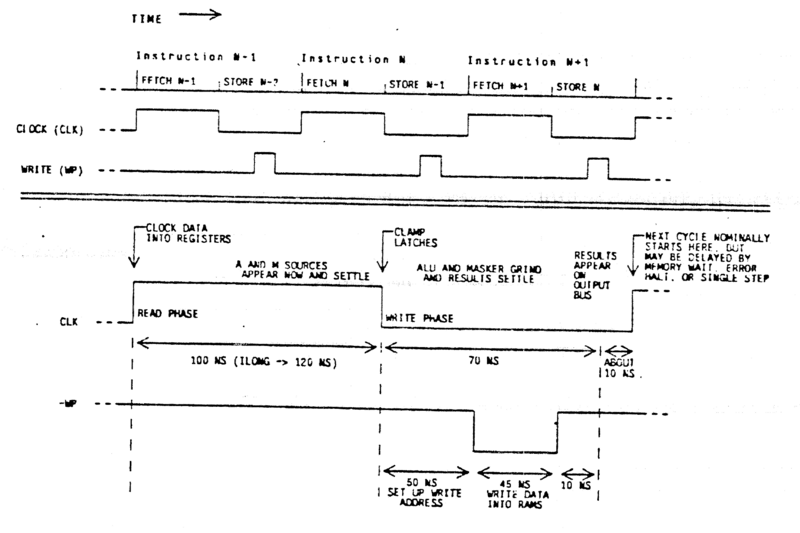
CADR Cycle Timing (source: MIT AI Memo 528)
The top diagram in the figure above shows fetch of the next microinstruction and store (or execute) of the current instruction in the same cycle, but in different halves of the clock.
The bottom diagram in the figure above shows the read and write phases and the typical cycle times.
Control and Data Paths
The control paths (things involving PC) of the CADR processor are shown below.
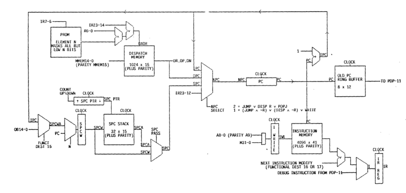
CADR Processor Control Paths (source: MIT AI Memo 528)
You can see the dispatch memory (DPC) on top left, the SPC stack on bottom left, and the instruction memory on bottom right.
The data paths of the CADR processor are shown below.
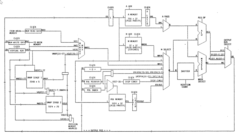
CADR Processor Data Paths (source: MIT AI Memo 528)
You can see the A scratchpad (top middle), the M scratchpad (top middle), and the PDL buffer (bottom middle). Both the A and M buses are 32-bits. The A bus is reserved for the A scratchpad, but in addition to the M scratchpad, many things can be on the M bus. (see Microinstructions for more info)
The output of an execution can be directed to (or, in other words, the output bus is connected to) many things. (see Microinstructions for more info)
The output can also be sent to the Q register, but it is selected differently.
Virtual Memory
CADR processor has 22-bit physical address space (2^22=0x400000) and it is organized like this:
| Physical Address Range | Device |
|---|---|
| 3E0000:3FFFFF | Unibus |
| 3C0000:3DFFFF | Xbus I/O |
| 000000:3BFFFF | Xbus memory |
Because the Unibus is 16-bit, only the low 16 bits (15:0) of the 32-bit data bus is used.
The VMA (virtual memory address) and MD (memory data) register are used for all operations on Unibus and Xbus, not only for main memory.
- VMA register is 24-bit wide (actually 32-bit but 8-bit is ignored)
- MD register is 32-bit wide
Unibus and Xbus is accessed by a two-level virtual memory system, which maps a 24-bit virtual address into a 22-bit physical address.
The first level map has 2048 5-bit wide locations. It is addressed by VMA[23:13] or MD[23:13] (10-bit wide addressing for 2048 locations).
The second level map has 1024 14-bit wide locations. It is addressed by the concatenation of first level map output (5-bit) and by VMA[12:8] or MD[12:8] (10-bit wide addressing for 1024 locations).
The virtual address space consists of 2048 blocks (11-bit addressing), and 32 pages (5-bit addressing) in each block, and 256 (8-bit addressing) words in each page (11+5+8=24). The first level finds the block. The second level finds the page. The physical address is the concatenation of the physical page number (14-bit, 16K pages) and VMA[7:0] (8-bit, 256 words/page).
Virtual Address (24-bit)
----------------------------------------------------
|23                  13|12       8|7              0|
----------------------------------------------------
          |                  |            |
          |                  |            |
          | (11-bit)         |            |
          |                  |            |
    +----------------+       |            |
    | LEVEL 1 (2048) |       |            |
    +----------------+       |            |
          |                  |            |
          | (5-bit)          | (5-bit)    |
          |                  |            |
        +----------------------+          |
        |    LEVEL 2 (1024)    |          |
        +----------------------+          |
                |                         |
                | (14-bit)                | (8-bit)
                |                         |
              +-----------------------------+
              |  Physical Address (22-bit)  |
              +-----------------------------+

MD can also be used for VMA[23:13] and VMA[12:8].

There are 2048 blocks, 32 pages/block, 256 words/page.
The output of the second level map also includes access (read) and write permissions for the page.
Because the second level map only has 1024 locations (1024 pages=32 blocks), only 32 blocks can be described. So, most of the entries in the first level map should point to a “no information available” entry. This is done by reserving the last 32 locations of the second level map with a “no information available” record. Most of the first level map entries point to these “no information available” records. It is the last 32 entries because the first 5-bit comes from the output of the first level map, it will be independent of the value of VMA[12:8].
Instruction Stream Feature
It is still not clear to me how this exactly works; I will update this section when I learn more.
I took the name of this section, “Instruction Stream Feature”, directly from MIT AI Memo 528.
There is obviously a need to coordinate the “interpretation” of the macroinstructions with the microinstructions. After the boot is completed, the interpretation of the macroinstructions should start.
To fetch a macroinstruction from the main memory, LC divided by 4 (word boundary) is transferred to the VMA and a memory read cycle is started. This returns a word to MD, and the correct half-word is selected by the M-rotate field. LC is incremented by 2 (LISP macroinstructions are half-word) because it always points to the next macroinstruction.
The end of a macroinstruction execution is signaled by a RETURN from the SPC stack when the bit-14 of the SPC entry is set. This initiates a new macroinstruction fetch.
Microinstructions
I minimized the information on this section. For more information, please check the original MIT CADR documents or usim/ucode.c source code.
CADR processor has only 4 microinstructions (2-bit opcode field). They are more like instruction groups that can do different things depending on the bit fields. The four opcodes are:
- Opcode 0: ALU. Destination receives the result of a boolean or arithmetic operation.
Example: A_memory[1] = A_memory[1] + M_memory[2]
- Opcode 1: (CONDITIONAL) JUMP. Transfer of control conditional on different things.
Example: If (A_memory[1] > M_memory[2]) jump PC+10
- Opcode 2: DISPATCH. Transfer of control based on an entry in dispatch memory, addressed by 7-bits of a byte in the M bus.
Example: Call subroutine at Dispatch_Memory[M_memory[0] + 10]
- Opcode 3: BYTE. Destination receives the result of a byte extraction, byte deposit, or selective field substitution from one source to another. This works by a rotation and a mask combination.
Example: A_memory[1] = (A_memory[1] & 0xFFFFFF00) | (M_memory[2] & 0x000000FF)
The format of these instructions is very regular.
All instructions have these fields:
- an odd parity bit
- statistics bit; when set, the statistics counter is incremented
- ILONG bit; indicates a longer write phase for the clock
- 2 bits Opcode (0=ALU, 1=JUMP, 2=DISPATCH, 3=BYTE)
- a bit to indicate POPJ transfer
- (source 1) A bus select: A memory address
- (source 2) M bus select: M memory address or a functional source
- 2 bits miscellaneous function select
- destination can be A memory or a functional destination
Basically, it is similar to this:
   +---------------------------------------+
   |                                       |
   |                       +-----------+   |
A memory --------------A-->|           |---+
                           | Micro     |   |
M memory -----------+      | Operation |   |
                    |--M-->|           |   |
Functional source --+      +-----------+   |
   or destination                          |
   |                                       |
   +---------------------------------------|
(as a reminder, M memory is actually the first 32 locations of A memory)
The functional source on the M bus can be many things:
- 0x00: Dispatch constant (10 bits)
- 0x01: SPC pointer (5 bits), SPC data (19 bits)
- 0x02: PDL pointer (10 bits)
- 0x03: PDL index (10 bits)
- 0x05: PDL buffer, addressed by index
- 0x06: OPC registers (14 bits)
- 0x07: Q register
- 0x0A: VMA (virtual memory address) register
- 0x0B: Virtual Memory Map[MD]
- 0x0C: MD (memory data) register
- 0x0D: LC (location counter)
- 0x0E: SPC pointer and data, pop
- 0x14: PDL buffer, addressed by pointer, pop
- 0x15: PDL buffer, addressed by pointer
Functional destination can be many things:
- 0x00: None
- 0x01: LC (location counter)
- 0x02: Interrupt Control on bits 29:26
- 0x08: PDL, addressed by pointer
- 0x09: PDL, addressed by pointer, push
- 0x0A: PDL, addressed by index
- 0x0B: PDL index
- 0x0C: PDL pointer
- 0x0D: SPC data, push
- 0x0E: Next instruction modifier (OA register), bits 25:0
- 0x0F: Next instruction modifier (OA register), bits 47:26
- 0x10: VMA (virtual memory address) register
- 0x11: VMA register, start main memory read
- 0x12: VMA register, start main memory write
- 0x13: VMA register, write MAP*
- 0x18: MD (memory data) register
- 0x19: MD register, start main memory read
- 0x1A: MD register, start main memory write
- 0x1B: MD register, write to Virtual Memory Map
Table below shows the normal ALU operations:
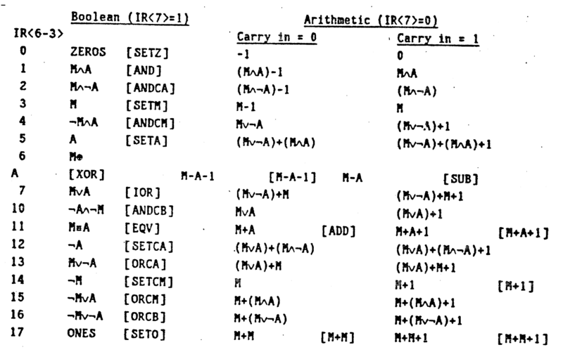
CADR Processor ALU Codes (source: MIT AI Memo 528)
It is also possible to make: multiply, divide, remainder correction, and initial divide steps with conditional ALU operation codes.
BYTE instruction also has these fields:
- a bit to indicate Mask rotate
- a bit to indicate Source rotate
- fields to indicate length and rotation count
BYTE instruction operates on a single byte of A and M sources. M source is taken as it is, optionally rotated to produce R. A selector mask is produced based on the rotation count and the length. This mask is used to merge the A source with R bit by bit (if mask bit=0, use A, otherwise, use R). The result of the merge operation is written back to the destination. The selector mask basically has ones starting from bit number rotation count for length+1 bits.
LISP Macrocode
Before jumping to macroinstructions, it will be useful to explain how LISP programs and LISP data are represented.
Program Representation
A program in the LISP machine can have one of the three representations:
Interpreted LISPis the same as textual LISP code input. However, this is the slowest form of execution, so it is only used for debugging etc.Compiled LISPis the macrocode representation of LISP programs. It still contains the checks of interpreted code, so it is usually normal to compile every program after typing in the editor.Microcodeis the other representation. These are the microprograms that execute macroinstructions or programs that perform low-level system tasks. Some of these cannot be done in LISP because they are very low-level. Some can be done in LISP, but they are hand tuned at the microcode level to have the best performance.
It is possible to “microcompile” a LISP function to a microcode to have the best performance if needed. However, instruction memory holding the microcode is limited (16K), so only a few microcompiled functions can be loaded at a time.
Data Representation
This section is incomplete. It is only meant to give a sense of how data is represented in LISP.
LISP objects are represented by a 5-bit data type field (32 possible data types) and a 24-bit pointer. 24-bit is because CADR has 24-bit virtual addresses. Most of the 32 data types are defined, and they have names like DTP-LIST, DTP-SYMBOL, DTP-FIXNUM etc.
A symbol is stored in four consecutive words. These four words are:
- PRINT NAME cell which holds a string object
- VALUE cell which contains the current value of the symbol
- FUNCTION cell which contains a function to be evaluated when needed
- PROPERTY LIST cell which contains the property list
The data type of symbol object is DTP-SYMBOL.
A list object has a data type DTP-LIST, and normally, it points to a two-word structure. The first word contains the CAR (first element), and the second contains the CDR (a list containing the rest of the elements). Since a LISP object is only 29 bits (5-bits data type and 24-bits address), two of the remaining bits (because the word is 32-bits) are used to optimize storage and to form a compressed list representation. These two bits are called CDR-CODE and can have the following values:
- CDR-NORMAL: indicates the two-word use as described above, the two-word structure keeps CAR and CDR.
- CDR-NEXT and CDR-NIL: indicate the list is stored as a vector, where the first word is the element (the value), and the second word points to the next two-word (when CDR-CODE=CDR-NEXT) or marks that this is the last element (CDR-CODE=CDR-NIL).
- CDR-ERROR: indicates the address should not be in the list.
Normally, the compressed representation is used unless RPLACD is called on a list.
There are three data types for number objects:
- DTP-FIX: represents 24-bit signed integers. The pointer part of the object contains the actual value.
- DTP-EXTENDED-NUMBER: represents other types of numbers such as floating point, arbitrary precision integers, complex numbers etc. The pointer points to the actual storage of the number.
- DTP-PDL-NUMBER: similar to DTP-EXTENDED-NUMBER but these stay only on the PDL buffer.
There is also a “locative pointer” data type, which is an actual pointer to a memory location. This is used for low-level system programming needs.
LISP Macrocompiler
The LISP macrocompiler, called QCMP, compiles a LISP function to macrocode. This “macrocompilation” process is so simple and straightforward that it is not necessary to save the compilation result. It can be used like a just-in-time compiler.
It is also unnecessary to write macrocode manually because it brings no benefits. Macrocode is well-matched to LISP, so instead of writing macrocode manually, the actual LISP function should be written and compiled.
When a function is macrocompiled by QCMP, a Function Entry Frame (FEF) is produced, and the compiled function is represented by a LISP symbol object whose FUNCTION cell contains a pointer to FEF, which is an object of type DTP-FEF-POINTER.
FEF contains:
- a header; which is always present, 7 words long
- pointers to external objects needed by the function: pointers to VALUE cells and FUNCTION cells
- description of arguments: the Argument Description List (ADL) which contains one entry to each argument.
- actual macroinstructions, the macrocode of the LISP function
Macroinstructions
This section is incomplete and is provided only to give a sense of macroinstructions. However, it is also not yet in a state that I am happy with; I am still working on it. For more information, please check the original MIT CADR documents or usim/ucode.c source code.
Each macroinstruction is 16-bits. LC points to macrocode in main memory (like PC points to microcode in instruction memory), and LC is incremented by 2 after each fetch because LC has byte-addressing not word-addressing.
Macrocode is executed on a stack-oriented machine. The stack (do not confuse this with SPC or other things within the processor related to the execution of microinstructions) is organized as frames. Each frame contains the arguments, the local variables, a stack for intermediate results, and various other information. The current frame is always in the PDL buffer, so there is no need to access main memory for the arguments and the local variables. Other frames can also be kept in the PDL buffer for performance.
Macroinstructions are grouped into four classes (plus a reserved class).
This is the basic form of macroinstructions:
------------------------------------
|15  13|12     9|8                0|
------------------------------------
         OPCODE
If macroinstruction[12:9]/OPCODE field is:
- 0x9, 0xA or 0xB: Class II
- 0xC: Class III
- 0xD: Class IV
- 0xE or 0xF: Class V - Reserved
- otherwise: Class I
Class I - Data Transmission and Function Calling
-------------------------------------
|  3   |   4    |  3   |     6      |
-------------------------------------
  DEST   OPCODE REGISTER   OFFSET
SOURCE, or effective address E, is calculated according to what REGISTER field says and OFFSET is added to it.
REGISTER can be:
| REGISTER | FUNCTION | DESCRIPTION |
|---|---|---|
| 0 | FEF | starting location of FEF |
| 1 | FEF+100 | |
| 2 | FEF+200 | |
| 3 | FEF+300 | |
| 4 | CONSTANTS PAGE | page of widely used constants, such as T, NIL, small numbers etc. these are not repeated in each FEF and shared by all FEFs |
| 5 | LOCAL BLOCK | address of the local block on the PDL, used for addressing local variables |
| 6 | ARG POINTER | argument pointer into the PDL, used for addressing the arguments |
| 7 | PDL | offset must be 77, the top of the stack is popped and used |
DESTINATION can be:
| DEST | FUNCTION | DESCRIPTION |
|---|---|---|
| 0 | IGNORE | result is discarded, but flags are set |
| 1 | TO STACK | push result to the stack |
| 2 | TO NEXT | |
| 3 | TO LAST | |
| 4 | TO RETURN | return the result as the value of this function (return from subroutine) |
| 5 | TO NEXT, QUOTED | |
| 6 | TO LAST, QUOTED | |
| 7 | TO NEXT LIST |
There are 9 macroinstructions in Class I:
| OPCODE | INSTRUCTION | DESCRIPTION |
|---|---|---|
| 0 | CALL | call function, return value goes to DESTINATION |
| 1 | CALL0 | call a function with no arguments |
| 2 | MOVE | move the contents at effective address E to the DESTINATION |
| 3 | CAR | put the CAR of the contents at effective address E to the DESTINATION |
| 4 | CDR | put the CAR of the contents at effective address E to the DESTINATION |
| 5 | CADR | put the CAR of the contents at effective address E to the DESTINATION |
| 6 | CDDR | put the CAR of the contents at effective address E to the DESTINATION |
| 7 | CDAR | put the CAR of the contents at effective address E to the DESTINATION |
| 8 | CAAR | put the CAR of the contents at effective address E to the DESTINATION |
Class II - Arithmetic, Boolean, Comparison and Binding Operations
------------------------------------
|      7       |  3   |     6      |
------------------------------------
     OPCODE    REGISTER   OFFSET
Since there is no DESTINATION in these macroinstructions, the result is either pushed to the stack (like TO STACK or TO NEXT destination) or it is stored at the effective address. The calculation of effective address is the same as in Class I instructions.
Class II macroinstructions are further grouped into three subgroups. The subgroup number is encoded in OPCODE[2:0].
In the below tables, C(E) denotes the content at effective address E.
Subgroup 0x9 (11 octal) contains:
| OPCODE[6:3] | INSTRUCTION | DESCRIPTION |
|---|---|---|
| 0 | not used | |
| 1 | + | stack.push(stack.pop() + C(E)) |
| 2 | - | stack.push(stack.pop() - C(E)) |
| 3 | * | stack.push(stack.pop() * C(E)) |
| 4 | / | stack.push(stack.pop() / C(E)) |
| 5 | AND | stack.push(stack.pop() bitwise-AND C(E)) |
| 6 | XOR | stack.push(stack.pop() bitwise-XOR C(E)) |
| 7 | OR | stack.push(stack.pop() bitwise-OR C(E)) |
Subgroup 0xA (12 octal) contains these.
For the compare instructions below, C(E) is compared to top of the stack according to operation, and if the condition is true, NIL indicator is cleared, otherwise it is set. The stack is popped.
| OPCODE[6:3] | INSTRUCTION | |
|---|---|---|
| 0 | = | |
| 1 | > | |
| 2 | < | |
| 3 | EQ |
| OPCODE[6:3] | INSTRUCTION | DESCRIPTION |
| 4 | SCDR | stores CDR of C(E) to E |
| 5 | SCDDR | stores CDR of CDR of C(E) to E |
| 6 | 1+ | stack.push(stack.pop() + 1) |
| 7 | 1- | stack.push(stack.pop() - 1) |
Subgroup 0xB (13 octal) contains:
| OPCODE[6:3] | INSTRUCTION | DESCRIPTION |
|---|---|---|
| 0 | BIND | The cell at E is bound to itself. |
| 1 | BINDNIL | The cell at E is bound to NIL. |
| 2 | BINDPOP | The cell at E is bound to a value popped off the stack. |
| 3 | SETNIL | Store NIL in E. |
| 4 | SETZERO | Store fixnum 0 in E. |
| 5 | PUSH-E | Push a locative pointer to E on the stack. |
| 6 | MOVEM | Move the data on top of the stack to E. |
| 7 | POP | Pop the top of the stack into E. |
Class III - Branching
------------------------------------
|  3   |   4    |        9         |
------------------------------------
 BRANCH  (14)          OFFSET
  CODE

* second field always contains 0xC (octal 14)
Class III macroinstructions are:
| BRANCH CODE [2:0] | INSTRUCTION | DESCRIPTION |
|---|---|---|
| 0 | ALWAYS | Always branch |
| 1 | NILIND | Branch if the NIL indicator is set, else drop through |
| 2 | NOT NILIND | Branch if the NIL indicator is not set, else drop through |
| 3 | NILIND ELSE POP | same as NOT NILIND but if fails stack is popped |
| 4 | NOT NILIND ELSE POP | same as NOT NILIND ELSE POP but if fails stack is popped |
| 5 | ATOMIND | Branch if the ATOM indicator is set, else drop through |
| 6 | NOT ATOMIND | Branch if the ATOM indicator is not set, else drop throught |
If branch is to be taken, offset is considered as a signed offset and it is added to the PC. However, if the offset is 777, it is considered a long branch and the real offset is in the next halfword (16-bit). The PC added to is always the incremented PC, +1 in short branch and +2 in the long branch.
Class IV - Miscellaneous Functions
------------------------------------
|  3   |   4    |        9         |
------------------------------------
  DEST   (15)         OPCODE

* second field always contains 0xD (octal 15)
DESTINATION field is used as same as Class I macroinstructions.
Class V - Reserved
The instructions containing octal 16 and 17 (0xE and 0xF) in the second field of macroinstruction format as in Class III and Class IV are reserved.
Examples
These examples are to be run on CADR emulation.
Disassembling a LISP function to Macroinstructions
Disassembling is a strange word to use for this purpose, but what disassemble does is to macrocompile macrocompiling a LISP function, then disassemble the macrocompiled function, and display the macroinstructions.
A simple example:
(disassemble (lambda (x y) (+ x y)))
Definition of closed-over function
 14 MOVE D-PDL ARG|0          ;X
 15 + ARG|1                   ;Y
 16 MOVE D-RETURN PDL-POP
Line by line:
14 MOVE D-PDL ARG|0 | STACK.push(argument_0=X) |
15 + ARG|1 | STACK.push((add STACK.POP() argument_1=Y)) |
16 MOVE D-RETURN PDL-POP | RETURN STACK.POP() |
Compiling a LISP function
To macrocompile a LISP function, compile can be used.
The representation of a LISP function can be checked with describe function. For a macrocompiled function (Compiled LISP), it returns the function definition as a DTP-FEF-POINTER. For a microcompiled function (Microcode), it returns the function definition as a DTP-U-ENTRY. The function definition of an interpreted LISP function is LAMBDA or NAMED-LAMBDA.
See the example below:
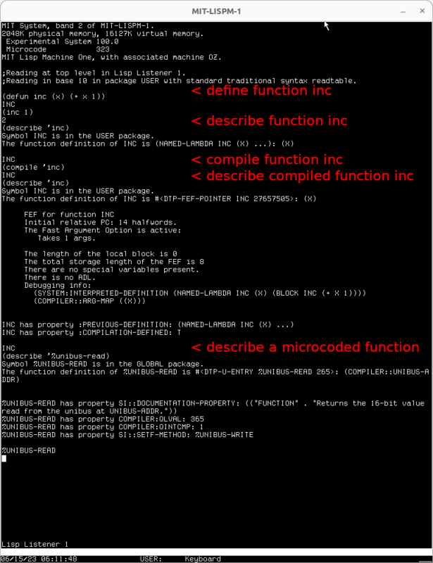
Interpreted, Compiled and Microcoded function descriptions
CADR Emulator
usim
The CADR software emulation is called usim. It was developed by Brad Parker between 2004 and 2006, and MIT gave permission and licensed the distribution of “recovered” CADR system software, including the microcode. I wrote recovered because the software was in old (backup) tapes, and the data in these old tapes had to be recovered.
An incomplete but valuable table shows the release history of actual CADR LISP Machine system software versions (including the microcode version). The latest version, dated 19 September 1983, and a release message from Richard Stallman, is System 97 (97.6) which requires microcode 257.
Note that the microcode version number was wrapped in ~1982; a smaller number does not mean it was released earlier.
You might wonder why the microcode version is also mentioned. The microcode has to be compatible with the system software. Other than the macroinstruction interpretation functions, there are low-level system-related functions within the microcode. A minor change in either microcode or system software might break the backward compatibility.
It seems Brad Parker’s active usim development ended in 2006, with v0.9 (2006-07-08) being the latest version. I am not sure what happened exactly after this, but looking at the changes, it seems Brad Parker made a minor fix in 2011, then a few different people made other changes. It seems like the latest codebase is at tumbleweed.nu as usim, and it is maintained by Alfred M. Szmidt who has been making changes since 2017.
History of the Restoration
(Thanks to Alfred M. Szmidt for the clarifications.)
First, LISP machine backup tape of System (version) 46 (and microcode version 694) was recovered. These tapes were found in Daniel Weinreb’s basement:
Lisp Machine System Software
Reel 1,2,3,4 10/17/81
9 track - 800bpi
ITS dump format

source: http://www.unlambda.com/mit/README
They are probably 2400ft tapes, since the tpc formatted extract of these tapes are over 10MB but less than 20MB. These files contain: system version 46, prom version 9 and microcode version 694.
However, there was no load band found for these tapes, so it cannot be used to boot a system. It contained the system source code and the schematics.
After some time, the tapes of System 78 are found also in Daniel Weinreb’s storage. This was the first loadable system. For a long time, this was the only system used with usim.
tape10i  2400  Distribution - 78.48     (source code for 78.48)
		       ZMail 38.5 Symbolics 8.13
		       Tape 6.5 LMFS 21.34
		       Microcode 841 1/11/82  BEE
		       "(added in pen - ""BROKEN!!"")"

tape11  2400  System 78.48 Band         (LOD1 band for 78.48)
		      1/12/82  BEE
		      "(in pencil - ""couldn't read 1/21/82  Roberts)"

source: https://tumbleweed.nu/r/attic/sys78/index
After a period of no development in this area, Alfred M. Szmidt found the tapes for a complete System 98, which could be used to boot a system. He then found an incomplete System 99 (TID/671 from MIT’s Tapes of Tech Square project), and he released System 100 based on System 99 after fixing a lot things. To be historically accurate, this is not a version a real CADR LISP Machine has ever run.
LM-3
LM-3 — resurrecting the MIT CADR is the project containing not only usim but also everything else such as the system software, microcode, PROM etc. to run an emulated MIT CADR LISP machine.
As mentioned above, LM-3 System 100 (microcode 323) is the latest version.
LM-3 System 100 release contains the following:
usim: CADR emulator source codechaos: Chaosnet for Unix source codesys: system software, PROM dump as well as PROM and microcode symbol filesdisk-sys-100-0.img: disk image containing microcode MCR and load band LOD partitionsusim-100-0.ini: sample configuration to use with usim
chaos is used (and required) when building usim. With the sample configuration, Chaosnet is run in “local” mode, and sys is mounted as tree on the LISP machine. PROM (microcode) file, PROM symbols, and microcode symbols are also in sys folder and used by usim.
Running usim with LM-3 is as simple as:
- download LM-3 System 100 release
- extract the downloaded file:
tar zxvf usim-2023-03-24.tar.gz - change the current directory into the usim source directory:
cd usim-2023-03-24/usim - build the CADR emulator: run
make, this will buildusim,diskmakerandreadmcrexecutables - change directory to parent:
cd .. - run usim with the supplied configuration:
./usim/usim -c usim-100-0.ini
On Ubuntu, build-essential and libx11-dev packages are needed to build usim. It is also possible to use the system software and disk image from LM-3 System 100 but use the latest source code of usim (and chaos) from their repositories -this is what I do-. The current development version of usim supports SDL2 (and also requires libsdl2-dev package).
It is possibly a must to check the Operating the Lisp Machine document to get a basic idea of this computer and how to use it.
Configuring usim
It is possible to build and run usim on the Windows Subsystem for Linux (WSL) running Ubuntu. With SDL2 support, it is not bad, but I think for the best experience it should be run on a virtual machine or on an isolated (physical) Linux computer. I used a virtual machine before but now I am using a small NUC.
There are two issues that you need to be aware of and address before being able to properly use the emulator.
4K/HiDPI Display
The usim source code in LM-3 System 100 release does not have support for scaling. It is not very possible to use usim tv output on such displays because the text is very small. The only solution is to use either a physical or a virtual display with a lower (1080p) resolution.
The latest usim source code do have SDL2 support and scaling, so it is possible to use it on 4K displays. This is currently what I am using with 2x scaling.
Keyboard Mapping
When using usim, a keyboard mapping is required because LISP machines use a special keyboard with many specially labeled function keys and additional modifier keys. There is a default mapping described below that can be further customized.
When you get serious about using the emulator, I highly recommend using a second keyboard, attaching this keyboard directly to the virtual machine, and putting the space-cadet labels on the keys. This is the keyboard I am using:
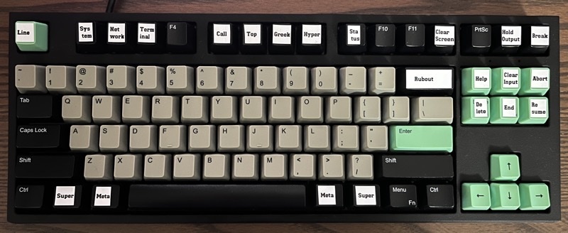
My CADR keyboard with space-cadet labels
The default mapping in usim source code is below:
| X11 Modifier | Cadet Key |
|---|---|
| Shift | Shift |
| Lock | Shift-Lock |
| Control | Control |
| Mod1 | Meta |
| Mod4 | Top |
| X11 Symbol | Cadet Key |
|---|---|
| Escape | altmode |
| F1 | system |
| F2 | network |
| F3 | status |
| F4 | terminal |
| F5 | help |
| F6 | clear |
| F7 | break |
| Insert | help |
| Home | break |
| End | End |
| Page_Up | Abort |
| Page_Down | Resume |
| Left | hand_left |
| Right | hand_right |
| Up | hand_up |
| Down | hand_down |
| Return | return |
| Tab | tab |
The character keys A-Z, 0-9, punctuation marks, and other symbols are mapped to the same ones by default.
The supplied ini file configures the keyboard as cadet and configures only two keys: F7 as integral and Mod4 as Super.
I use a different mapping, and this is in my ini file:
[kbd]
Escape = line
F1 = system
F2 = network
F3 = terminal
F4 = null
F5 = call
F6 = null # top
F7 = null # greek
F8 = null # hyper
F9 = status
F10= null
F11= null
F12=clear_screen
Scroll_Lock = hold_output
Pause       = suspend
BackSpace   = rubout
Insert      = help
Delete      = delete
Home        = clear_input
End         = end
Page_Up     = abort
Page_Down   = resume

[kbd.modifiers]
Shift   = Shift
Lock    = CapsLock
Control = Control
Mod1 = Meta
Mod2 = Greek
Mod3 = Hyper
Mod4 = Super
Mod5 = Top
When using X11 backend, the entries under kbd are in the form of X keysym = LM key. XStringToKeysym function is used to read X keysym. LM key means Lisp Machine key.
X keysym names are defined in the X11/keysymdef.h file in the system (e.g., /usr/include). For example, #define XK_BackSpace means there is a X keysym named BackSpace. The easiest way to check this is to use the xev utility and press the key.
When using SDL2 backend, the entries under kbd are in the form of SDL2 keysym = LM key. SDL_GetScancodeFromName function is used to read SDL keysym.
SDL keysym names are defined in the SDL2/SDK_keycode.h file as SDL_KeyCode enum values. For example, SDLK_BACKSPACE can be used as BACKSPACE (case-insensitive) in the config file.
Most of the X keysyms are the same as SDL2 keysyms, however, Scroll_Lock, Page_Up and Page_Down are ScrollLock, PageUp and PageDown.
LM keynames are defined in thelmch.defsfile. For example,X(suspend, 0201)inlmch.defsmeans there is anLM keynamedsuspend(which sends scan code octal 201 in the original keyboard). The function keys of (space-)cadet keyboard are these (ordered by the code in lmch.defs, between 201-236):break,clear_input,call,terminal,macro,help,rubout,overstrike,tab,line,delete,clear_screen,return,quote,hold_output,stop_output,abort,resume,status,end,roman_i,roman_ii,roman_iii,roman_iv,hand_up,hand_down,hand_left,hand_right,system,network.
These keys are a must to use the LISP machine:
help,rubout,abort,resume,end,system
It is not possible to use the CADR LISP machine without these keys (without a major hassle at least). You will probably also need:
terminal,clear_input,clear_screen,call,status
I also assign line to Escape; this goes to the next line (like pressing Return) and aligns the cursor position properly (like using Tab).
You most likely do not need these special keys unless you already know what you are doing:
quoteandstop_outputare not used by the system software. Maybe alsohold_output, but I am not sure.overstrikemoves the cursor back without deleting.deleteis not exactly specified. What we now know as delete is calledrubout.
Some function keys are reserved for user assignment, the system does not use them. Until you have a use for them, there is no need to map these keys:
hand_up,hand_down,hand_left,hand_right,roman_i,roman_ii,roman_iii,roman_iv
The entries under kbd.modifiers are in the form of X modifier = LM modifier. LM means lisp machine.
X modifiercan be:Shift,Lock,Control,Mod1,Mod2,Mod3,Mod4,Mod5LM modifiercan be:Shift,Top,Control,Meta,ShiftLockorCapsLock,ModeLock,Greek,Repeat,AltLock,Hyper,Super.
LISP machine system software does not distinguish between the left and right keys of the same modifier (Left-Control vs. Right-Control) except for warm-booting and cold-booting, but this is not used in the emulator.
ModeLock, CapsLock and AltLock keep their state. However, ModeLock and AltLock are not used by the system software.
At a minimum, you have to learn the locations of these modifiers: Shift, Control, Meta and Super.
Similar to the function keys mentioned above, Hyper modifier is also reserved for the user and not used by the system.
In addition to Shift, Top and Greek (also called Front) keys also modify the character keys to produce different characters. These are printed on top and on front of the keys (see the Symbolics keyboard image), hence their name. Greek is used for printing Greek or mathematical symbols, hence the name.
If you want to assign a normal key (such as F7) as an LM modifier (such as Greek), you have to first use xmodmap to assign F7 as a Mod (such as Mod2), and then assign Mod2 to Greek. It is not possible to assign F7 directly as Greek with usim. I use the following xmodmap file to set modifiers:
clear Mod1
clear Mod2
clear Mod3
clear Mod4
clear Mod5
add Mod1 = Alt_L Alt_R
add Mod2 = F7
add Mod3 = F8
add Mod4 = Super_L Super_R
add Mod5 = F6
The current modifier mapping of Linux can be displayed with xmodmap -pm.
Logging
To see a bit more log messages, I have these in my ini:
[trace]
level=info
facilities=x11 kbd usim
The defaults of trace section is level=notice and facilities=usim.
- level can be one of these:
emerg,alert,crit,err,warning,notice,info,debug. - facilities can be one of these:
all,none,usim,ucode,microcode,macrocode,int,vm,unibus,xbus,iob,kbd,tv,mouse,disk,chaos,x11,spy,lashup,misc.
Be aware that debug or even info level and certain facilities can output a lot of messages.
Testing usim
When you are done with the config file, you can run the emulator with usim -c usim.ini. You should see a window like this:
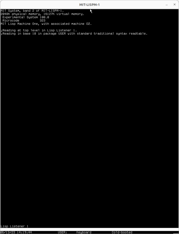
usim CADR emulator with LM-3 System 100
To halt the LISP machine, you can Ctrl-C the usim process on the terminal or use (sys:%halt) at LISP listener.
You can also try running a demo to check the installation by typing (hacks:crock) in LISP listener.
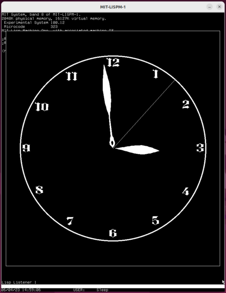
Crock demo
References
- Recursive Functions of Symbolic Expressions and Their Computation. MIT AI Memo 8, March 1959. Also published in Communications of the ACM in 1960.
- The LISP Machine. MIT Working Paper 79, November 1974
- CONS. MIT Working Paper 80, November 1974
- LISP Machine Progress Report, MIT AI Memo 444, August 1977
- History of LISP. ACM SIGPLAN Notices, Vol. 13, No. 8, August 1978
- Implementation of a List Processing Machine, MSc Thesis of Thomas F. Knight, January 1979
- The LISP Machine Macro-instruction Set. T. Knight, February 1979
- CADR. MIT AI Memo 528, May 1979
- CADR. MIT AI Memo 528, March 1981
- CADR. MIT AI Memo 528 with some mistakes fixed by S.Takeoka.
- Symbolics LM-2 Specifications. Not dated, ~1980
- Symbolics LM-2 Price List. October, 1980
- Symbolics LM-2 Brochure. Not dated, ~1980
- Operating the Lisp Machine. MIT Working Paper 209, April 1981
- Symbolics LM-2 Unibus I/O. September, 1981
- If It works, It’s Not AI: A Commercial Look at Artificial Intelligence Startups. BSc and MEng Thesis of Eve M. Phillips, May 1999
- My Lisp Experiences and the Development of GNU Emacs. Transcript of Richard Stallman’s speech at the International Lisp Conference, October 2002
- Dan Weinreb’s comments on Symbolics and Lisp Machines. Archive of three blog posts from November-December 2007.
- Lisp Machine Manual, Seventh Edition, System Version 99
This work is licensed under a Creative Commons Attribution-NonCommercial-ShareAlike 4.0 International License.